How Road Case Design Protects Equipment During Transport and Touring

Equipment that travels rarely fails because of poor operation. It fails because of poor packaging. Whether it is a construction survey rig heading to a remote site, a touring production’s lighting rack, or an architecture firm’s precision scanning equipment, the difference between arriving ready to work and arriving in for repair usually comes down to one thing: the case it travelled in. This is the discipline of Road Case Designer work – engineering enclosures that are built to absorb impact, resist environmental stress, and keep sensitive equipment stable through repeated handling. For firms that rely on expensive, calibrated, or fragile assets, understanding how this design process works is the first step to protecting a serious investment.

What Is Road Case Design?

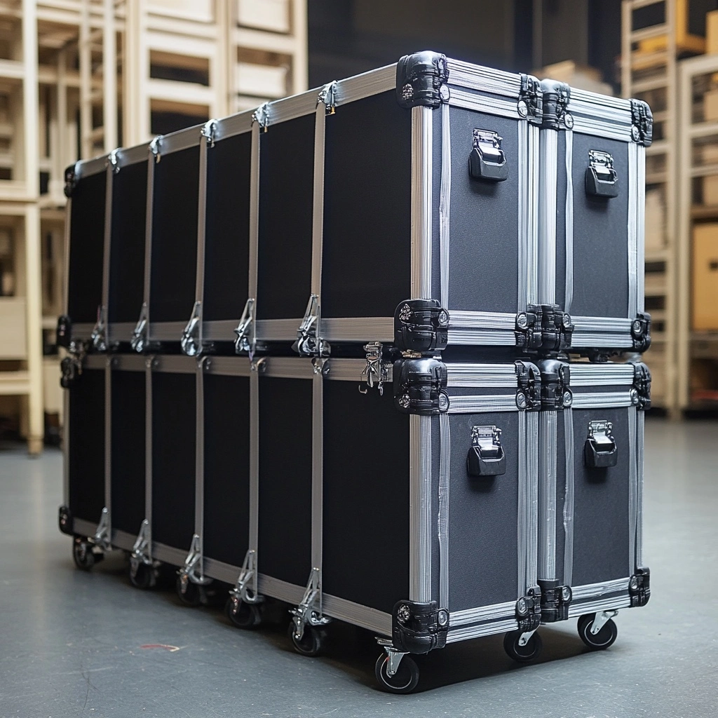
Road case design is the engineering process of building protective transit enclosures – often called flight cases – that shield equipment from shock, vibration, moisture, dust, and mishandling during transport. Unlike generic packaging, a road case is engineered around the exact dimensions, weight, and fragility of the item it carries.

A well-designed case does three jobs at once: it protects the contents, it makes the equipment easier to move and store, and it withstands years of repeated freight handling, stacking, and loading without failing. This combination of protection, usability, and durability is what separates professional road case design from standard shipping boxes.

Why Equipment Protection Matters During Transport and Touring

For engineering, construction, and architecture firms, equipment such as total stations, 3D scanners, drones, and testing instruments is often calibrated to fine tolerances. A single hard knock during freight handling can throw off readings long before anyone notices the fault.

Touring and event production equipment faces a different but equally demanding challenge: repeated loading and unloading, sometimes several times a week, over months. The cumulative wear from this cycle is what most often causes failures, not any single dramatic incident.

Poorly protected equipment leads to project delays, costly recalibration or replacement, and – in hiring and staffing terms – reputational risk for firms whose professionals turn up without functioning tools. Investing in proper transit protection is a practical risk-management decision, not an aesthetic one.

Core Engineering Principles Behind Effective Road Case Design

Professional case builders work to a set of established engineering principles rather than guesswork. These principles determine how a case behaves under real-world transport conditions.

1. Impact Absorption

Foam inserts, corner blocks, and internal cushioning are calculated to absorb and dissipate shock energy before it reaches the equipment, rather than transferring the full force of an impact directly to the contents.

2. Load Distribution

Weight must be spread evenly across the case base and reinforced corners. Uneven load distribution is a common cause of warping, hinge failure, and stress cracks over a case’s working life.

3. Vibration Isolation

Sustained low-level vibration from road or air freight can loosen fasteners and degrade sensitive electronics over time. Isolation mounts and layered foam reduce this transmitted vibration significantly.

4. Environmental Sealing

Gasket seals, weatherproof latches, and moisture-resistant panels protect against humidity, dust, and temperature swings, particularly relevant for outdoor construction sites or international touring.

Together, these principles form the foundation of every credible

Road Case Design project, regardless of whether the case is holding surveying instruments or stage lighting consoles.

Key Materials Used in Road Case Construction

Material choice directly affects a case’s strength-to-weight ratio, cost, and lifespan. Most professional cases combine several materials rather than relying on one.

  • Plywood shells: typically 9–12mm birch or poplar ply, offering strength and screw retention for hardware.
  • Aluminium extrusion edging: protects corners and edges, the most vulnerable points on any case.
  • ABS or polyethylene laminate: a durable, weather-resistant outer skin bonded to the plywood.
  • Foam inserts: closed-cell polyethylene or polyurethane foam, cut to the exact profile of the equipment.
  • Heavy-duty hardware: recessed butterfly latches, ball corners, and spring-loaded handles rated for repeated use.

The right combination depends on how the case will be used – a case that is loaded onto a truck twice a year has different requirements to one loaded and unloaded at a different venue every night.

How a Road Case Designer Approaches a Custom Build

A qualified road case designer does not start with a template. The process typically follows a structured sequence to ensure the finished case matches both the equipment and the way it will actually be used.

Step 1: Equipment Assessment

The designer records exact dimensions, weight, fragile points, and any ventilation or access requirements for the equipment in question.

Step 2: CAD Modelling

Using AutoCAD or equivalent design software, the internal layout, foam cutouts, and case shell are modelled precisely before any material is cut. This stage is where measurement errors are caught before they become costly.

Step 3: Prototyping and Testing

A prototype is built and, where appropriate, tested against drop, vibration, or load standards relevant to the equipment’s use case.

Step 4: Production and Finishing

The final case is manufactured, fitted with hardware, and finished with branding, labelling, or asset-tracking features as required.

This structured, CAD-led approach is why firms that rely on precision equipment increasingly look for designers with genuine engineering and drafting skill, rather than treating case-building as a simple carpentry task.

Common Risks During Transport and How Design Mitigates Them

Understanding the specific risks equipment faces in transit helps explain why each design choice matters.

  • Drops and impacts – mitigated by corner reinforcement, recessed hardware, and internal foam cushioning.
  • Compression from stacking – mitigated by rigid shell construction and load-bearing corner blocks.
  • Vibration during long-haul freight – mitigated by isolation foam and secure internal mounting.
  • Moisture and dust ingress – mitigated by gasket seals and weatherproof latch systems.
  • Repeated handling wear – mitigated by heavy-duty hinges, ball corners, and reinforced wheel assemblies.

None of these risks are eliminated entirely – they are managed to an acceptable, calculated level, which is the realistic goal of any transit protection system.

Best Practices for Choosing the Right Road Case

Firms evaluating case options, or hiring designers to build them, should look for a few consistent markers of quality work.

  • Custom internal fitting rather than generic foam padding.
  • Clear documentation of materials and hardware ratings.
  • Evidence of CAD-based design rather than freehand fabrication.
  • A track record with equipment of similar weight and fragility to your own.
  • Realistic guidance on maintenance and expected working life.

For a deeper walkthrough of the selection process, this guide to choosing a road case designer covers the questions worth asking before committing to a build.

Conclusion: Protecting Equipment Starts With Good Design

Reliable equipment protection during transport and touring is not accidental – it is the result of deliberate engineering decisions made long before a case is ever loaded onto a truck. From material selection to CAD-modelled internal fitting, every stage of the process exists to reduce risk to valuable, often irreplaceable, equipment.

For engineering, construction, architecture, and production teams that depend on their equipment arriving ready to work, Keyway applies exactly this kind of precision engineering approach to every case it designs, drawing on genuine CAD and drafting expertise rather than off-the-shelf templates. Firms exploring custom transit protection, or looking to bring skilled design capability into their own teams, can find further insight and updates via keyway on LinkedIn.

How AutoCAD Recruitment Agencies Solve Engineering Staffing Challenges

Finding skilled AutoCAD professionals has become one of the most persistent headaches for engineering, construction, and design firms. Vacancies sit open for months, project timelines slip, and in-house HR teams often lack the technical knowledge to properly vet CAD candidates. This is precisely why Autocad Recruitment Agencies have become such a valuable resource they combine deep technical understanding of drafting and design software with proven recruitment processes, helping firms fill critical roles faster and with far greater confidence. In this article, we’ll explore exactly how these agencies work, the problems they solve, and what firms should look for when choosing a staffing partner.

Why Engineering Firms Struggle to Hire AutoCAD Talent

Before looking at solutions, it’s worth understanding why this hiring challenge exists in the first place.

Demand consistently outpaces supply: Infrastructure, construction, and manufacturing projects continue to expand, yet the pool of drafters and designers with genuine AutoCAD proficiency hasn’t grown at the same rate.

Technical vetting is difficult for generalist recruiters: A candidate might list “AutoCAD” on their CV, but knowing the difference between someone who can competently produce construction documents and someone who has only used the software casually requires specialist knowledge.

Project timelines rarely allow for lengthy searches: Engineering and construction schedules are tight. A vacant drafting seat can delay approvals, permitting, and downstream construction work.

Short-term and project-based needs don’t suit permanent hiring: Many firms need CAD support for a defined project phase, not a permanent headcount addition, which makes traditional recruitment a poor fit.

What Is an AutoCAD Recruitment Agency?

An AutoCAD recruitment agency is a specialist staffing provider that sources, screens, and places CAD drafters, designers, and technicians for engineering, architecture, and construction firms. Unlike general recruitment agencies, these providers understand CAD workflows, industry-specific drawing standards, and the software proficiency levels required for different project types allowing them to match candidates to roles with far greater accuracy.

How These Agencies Solve Core Staffing Challenges

1. Technical Screening That Goes Beyond the CV

A generalist recruiter reads a CV. A specialist AutoCAD recruitment agency tests it. This typically includes:

  • Practical drafting assessments in AutoCAD, Civil 3D, or Revit
  • Review of past drawing sets and portfolios
  • Verification of discipline-specific experience (structural, MEP, civil, architectural)
  • Assessment of familiarity with drawing standards and layer conventions used in the client’s sector

This layer of technical screening significantly reduces the risk of a poor hire something an untrained recruiter simply cannot replicate.

2. Access to a Pre-Vetted Talent Pool

Specialist agencies maintain an active network of drafters and designers who are already screened, reference-checked, and in many cases previously placed successfully. This means firms aren’t starting from zero each time a role opens. Instead of a six-to-eight-week open search, a firm can often review qualified, vetted candidates within days.

3. Flexible Staffing Models

Not every project needs a permanent hire. Staffing agencies typically offer several engagement models to match the way engineering work actually happens:

  • Temporary or project-based staffing – for short-term surges in drafting workload
  • Temp-to-permanent arrangements – allowing firms to trial a candidate before committing
  • Direct-hire placements – for long-term, permanent positions
  • Staff leasing arrangements – where the agency employs the worker on the firm’s behalf, handling payroll, compliance, and administration while the professional works under the client’s day-to-day direction

This last option, known as Staff Leasing Services, is particularly useful for firms that want dedicated CAD support without the administrative burden of direct employment a model worth understanding in more detail if your firm regularly scales teams up and down with project demand.

4. Reducing Time-to-Hire

Speed matters in engineering staffing. A specialist agency shortens the hiring cycle by handling sourcing, screening, interview coordination, and reference checks in parallel rather than sequentially. Firms typically see candidates presented within days rather than weeks, because the agency isn’t starting the search cold it already has relevant professionals in its network.

5. Managing Compliance and Administrative Burden

Employment compliance contracts, payroll taxes, benefits administration, and local labour regulations is time-consuming and carries legal risk if handled incorrectly. When firms use a staffing or staff leasing arrangement, the agency typically assumes responsibility for:

  • Payroll processing and statutory deductions
  • Employment contracts and documentation
  • Workers’ compensation and insurance coverage
  • Ongoing compliance with local labour law

This allows engineering and construction firms to focus on project delivery rather than HR administration.

What to Look for When Choosing an AutoCAD Recruitment Partner

Not all staffing agencies are equipped to serve technical industries. When evaluating a potential partner, consider the following.

Does the Agency Understand Your Discipline?

An agency placing structural drafters should understand the difference between structural steel detailing and architectural drafting. Ask about their experience placing candidates in your specific discipline civil, MEP, structural, or architectural.

How Do They Assess Technical Skill?

Ask directly what their screening process involves. A credible agency should be able to describe practical testing methods, not just CV keyword matching.

What Engagement Models Do They Offer?

Firms with fluctuating project pipelines benefit from agencies offering flexible arrangements temporary, contract, direct-hire, and staff leasing rather than a one-size-fits-all placement service.

What Is Their Track Record?

Ask for examples of similar placements, average time-to-fill for comparable roles, and how they handle a poor-fit placement (many reputable agencies offer a replacement guarantee within a defined period).

Best Practices for Working With an AutoCAD Staffing Agency

To get the most value from a recruitment partnership, firms should:

  1. Provide a detailed role brief – including software version, discipline, drawing standards, and project duration.
  1. Clarify the engagement type upfront – temporary, contract, or permanent – so the agency sources appropriately.
  1. Involve technical staff in final interviews – the agency handles initial screening, but a technical lead should confirm fit before an offer is made.
  1. Set clear onboarding expectations – particularly for project-based hires who need to be productive quickly.
  2. Maintain an ongoing relationship – firms with recurring CAD staffing needs benefit from an agency that understands their standards and preferences over time, rather than starting fresh with each vacancy.

Final Thoughts

Engineering, construction, and design firms don’t need to accept lengthy vacancies, mismatched hires, or the administrative weight of managing project-based staff alone. Specialist AutoCAD recruitment agencies address these challenges directly, combining technical screening, flexible engagement models, compliance support, and LinkedIn to help firms build capable drafting and design teams without the usual friction.

For firms seeking a staffing partner that understands the technical demands of engineering and construction recruitment, KEYWAY offers the industry expertise, vetted talent network, and flexible staffing solutions needed to solve CAD hiring challenges reliably and efficiently. You may also find it useful to read more on how a CAD recruitment agency helps find certified designers for a closer look at the vetting process behind certified CAD talent.

How Finite Element Analysis Services Prevent Costly Design Failures

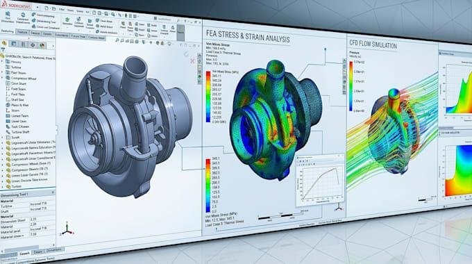
Every product failure that reaches a customer costs far more than one caught on a screen. That’s why more manufacturers now rely on professional Finite Element Analysis Services to simulate real-world stress, vibration, thermal load, and fatigue before a single physical prototype is built. Instead of discovering a weak weld, an overstressed bracket, or a fatigue crack after tooling is cut, engineering teams can identify and correct these issues digitally saving weeks of rework and thousands of dollars in scrapped parts.

What Is Finite Element Analysis (And Why It Matters)

Finite Element Analysis (FEA) is a computational method that breaks a complex part or assembly into thousands of smaller elements, then calculates how each element behaves under load, heat, vibration, or pressure. According to Wikipedia, the finite element method is a numerical technique used to find approximate solutions to boundary value problems for partial differential equations, widely applied in structural, thermal, and fluid analysis across engineering disciplines.

In practical terms, FEA lets engineers answer questions like:

  • Will this bracket crack under repeated vibration?
  • Where will stress concentrate on this weld joint?
  • Can this enclosure survive a drop test?
  • Will this assembly deform under thermal expansion?

Answering these questions before manufacturing is what separates a reliable product launch from an expensive recall.

How Design Failures Happen Without Simulation

Most costly design failures don’t come from bad engineering they come from untested assumptions. Common failure points include:

  1. Stress concentrations at sharp corners, holes, or fillets that aren’t visible until the part physically cracks.
  1. Fatigue failure from cyclic loading that only shows up after thousands of load cycles in the field.
  2. Thermal expansion mismatches between materials that cause warping or seal failure.
  3. Assembly-level interactions where individual parts pass inspection but fail once combined under real operating loads.

Physical prototyping alone often misses these issues because a prototype only reveals that something failed not why, or where the margin actually was.

Where FEA Analysis Solidworks Assembly Simulation Fits In

For teams already designing in SolidWorks, running FEA Analysis Solidworks Assembly simulations directly on the CAD model is one of the most efficient ways to validate a design before it leaves the digital environment. Because the simulation works from the native assembly file, engineers can:

  • Test multiple load cases on the full assembly, not just isolated parts
  • Identify how components interact bolted joints, press fits, contact surfaces
  • Iterate on geometry changes and immediately re-run analysis without rebuilding a prototype
  • Catch interference or stress issues introduced by tolerances between mating parts

This assembly-level view matters because failures rarely happen in a single component in isolation they happen at interfaces, joints, and load paths between parts.

The Business Case: Why FEA Pays for Itself

Without FEA

With FEA Services

Multiple physical prototype rounds

Fewer prototypes, validated digitally first

Failures discovered late, near production

Failures caught early, in the design phase

Field failures and warranty claims

Reduced risk of in-service failure

Overdesigned parts (excess material “just in case”)

Optimized geometry lighter, cheaper, still safe

The cost of a single late-stage tooling change often exceeds the entire cost of a simulation study. This is the core economic argument for building FEA into the design workflow rather than treating it as an optional final check.

Common Applications of FEA in Product Design

  • Structural analysis – verifying load-bearing components won’t yield or buckle
  • Fatigue analysis – predicting part life under repeated stress cycles
  • Thermal analysis – modeling heat distribution in enclosures, electronics, and engines
  • Vibration and modal analysis – identifying resonance frequencies that could cause failure
  • Drop and impact simulation – testing durability for consumer and industrial products

How the FEA Process Works, Step by Step

A professional simulation study isn’t a single button press it’s a structured process, and understanding it helps engineering teams know what to expect when they bring in outside FEA support.

  1. Model preparation – The CAD geometry is cleaned up and simplified where needed. Small features that don’t affect structural behavior (cosmetic fillets, logos, non-load-bearing holes) are often removed to keep the mesh manageable without sacrificing accuracy.
  1. Meshing – The part or assembly is divided into thousands (sometimes millions) of small elements. Mesh density is increased in high-stress areas like fillets, joints, and contact surfaces, and kept coarser elsewhere to balance accuracy with computation time.
  2. Defining materials and boundary conditions – Real material properties (yield strength, elastic modulus, thermal conductivity, fatigue curves) are assigned, along with how the part is constrained and loaded bolted supports, applied forces, pressure, temperature, or vibration input.
  3. Running the solver – The software calculates stress, strain, displacement, or temperature distribution across every element based on the defined loads and constraints.
  4. Post-processing and interpretation – Results are reviewed as color-coded stress or displacement plots, and an experienced analyst checks whether high-stress regions make physical sense or indicate a modeling error that needs correction.
  5. Design iteration – If the part fails to meet its safety factor, geometry, material, or wall thickness is adjusted and the simulation is re-run often multiple times until the design meets its performance target.

This iterative loop is where most of the cost savings come from: each iteration in software takes hours, while each iteration with physical prototypes can take weeks and consume material, tooling, and lab time.

Real-World Scenario: Catching a Failure Before It Happens

Consider a common example a sheet metal bracket designed to hold an electronic enclosure on a vehicle subject to constant road vibration. On paper, the bracket looks adequately sized. A static load calculation shows it can support the enclosure’s weight with margin to spare.

Run through FEA, however, a different picture emerges. The simulation reveals a stress concentration at a mounting hole that experiences amplified load during resonance at a specific vibration frequency the vehicle regularly encounters. Under static loading alone, this issue would never surface. Under real-world cyclic loading, it would eventually lead to a fatigue crack likely discovered only after units are already in the field.

By catching this in simulation, the engineering team can add a small fillet radius, adjust hole placement, or increase material thickness in just that region a change that costs almost nothing in software but would have triggered a field recall if it had reached production.

Choosing the Right FEA Services Partner

Not all simulation work delivers the same value. When evaluating a provider for Finite Element Analysis services, engineering teams should look for:

  • Experience with your specific application – aerospace fatigue analysis requires different expertise than consumer electronics thermal modeling.
  • Ability to work directly with your CAD platform – including SolidWorks assemblies, so results map directly back to the design without translation errors.
  • Clear reporting, not just colorful stress plots a good analysis explains why a result matters and what design change addresses it.
  • Validation experience – providers who understand how simulation results correlate with physical test data tend to produce more trustworthy, actionable results.
  • Turnaround time that fits your design cycle, since simulation only saves money if it happens early enough to influence decisions.

Best Practices for Getting Accurate, Useful Results

Simulation is only as reliable as the assumptions behind it. A few practices consistently separate useful FEA studies from misleading ones:

  • Use realistic material data rather than generic default values, especially for plastics, composites, and welded joints where properties vary significantly by manufacturing process.
  • Apply loads and constraints that reflect actual in-service conditions, not just idealized worst-case static loads.
  • Refine the mesh in critical regions rather than uniformly across the whole model, which keeps results accurate without excessive solve time.
  • Cross-check simulation results against hand calculations or known benchmarks for a sanity check before trusting the output.
  • Treat FEA as part of an iterative design process, not a one-time pass/fail gate at the end of development.

Final Thoughts

Design failures are rarely a surprise in hindsight; they’re usually the result of a load path, joint, or material limit that was never tested before production. Building simulation into the design cycle, rather than treating it as a final formality, is what allows engineering teams to catch these issues while they’re still cheap to fix. LinkedIn can also help engineering teams stay connected with industry insights, technical discussions, and emerging simulation practices. That’s the value KEYWAY brings to product teams: turning simulation data into design decisions before a single part is cut, so what reaches manufacturing has already proven it can hold up in the real world.

How Reverse Engineering Tools Mechanical Improve Product Development

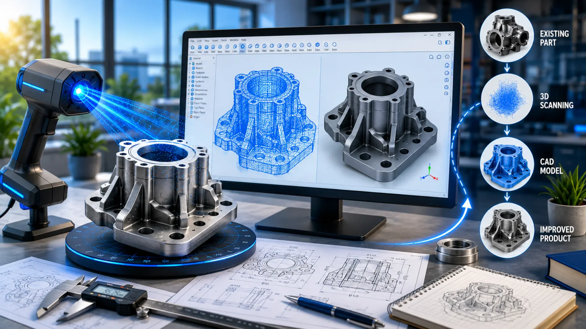
Product teams face constant pressure to launch faster, cut costs, and fix design flaws before they reach the market. Reverse engineering gives engineers a practical way to meet all three goals at once. By scanning an existing part, mechanical teams rebuild accurate digital models, study hidden geometry, and improve designs without starting from zero. Companies that offer professional Reverse Engineering Services help manufacturers turn physical parts into usable CAD data quickly. This process saves time, reduces guesswork, and gives engineers a solid foundation to build better products.

What Is Reverse Engineering in Mechanical Design?

Reverse engineering means taking an existing physical object and working backward to understand how it was built. Engineers scan the part, capture its exact shape, and convert that data into a 3D CAD model. This model shows dimensions, tolerances, and material properties that the original design files may have lost or never had. Mechanical teams use this approach when original drawings go missing, when a supplier discontinues a part, or when they need to improve an outdated design. Instead of measuring every surface by hand, engineers rely on digital tools to capture accurate data within hours instead of weeks.

The Data: What Reverse Engineering Actually Delivers

The time and cost savings from scan-based reverse engineering aren’t just anecdotal – they show up clearly in vendor benchmarks and case studies:

  • 3D scanning can reduce the analysis and design validation portion of reverse engineering by up to 80% compared with traditional manual measurement methods (FARO).
  • One documented case of a manufacturer and distributor of construction machine spare parts saved 85% in time and cost after switching to scanner-based reverse engineering instead of manual measurement.
  • A process that once took multiple days of manual measurement and drafting can now be completed through a scan-to-CAD workflow in roughly 2 to 8 hours, including scan setup, processing, and export.
  • Modern 3D scanners capture geometry with accuracy down to 0.02–0.05 mm, which is precise enough for most mechanical and industrial tolerance requirements, including aerospace and medical applications.

At a glance:

MetricReported ImprovementSource
Analysis & validation time cutUp to 80%FARO
Time & cost savings (case study)85%Industry case data
Manual measurement vs. scan-to-CADMulti-day → 2–8 hrsScan-to-CAD workflow benchmarks
Scanning accuracy0.02–0.05 mm3D scanner manufacturer specs

Why Manufacturers Turn to Reverse Engineering Tools

Manufacturers face several problems that reverse engineering solves directly. Old machines often run on parts that no longer exist in any catalog. Some parts changed hands between companies so many times that nobody kept the original specifications. In other cases, a competitor’s product performs better, and the team wants to understand why. Reverse engineering tools give engineers a way to answer these questions without disrupting production. Scanning technology captures every curve and surface with precision, so teams can recreate a part or redesign it entirely. This approach also helps companies avoid expensive downtime, since they can produce a replacement part fast instead of waiting weeks for a new order from an original supplier.

Core Reverse Engineering Tools Mechanical Teams Rely On

Modern shops use several types of Reverse Engineering Tools Mechanical teams need to capture and rebuild parts. 3D laser scanners create detailed point clouds that map every surface of an object. Structured light scanners work well for smaller, more detailed components that need tighter tolerances. Coordinate measuring machines check dimensional accuracy once a scan is complete. CAD software then converts raw scan data into usable solid models that engineers can edit, test, and refine. Some teams also use CT scanning to capture internal geometry without cutting a part open. Together, these tools give mechanical engineers a complete picture of a component, inside and out, so they can validate designs, spot flaws, and move confidently into production.

How These Tools Speed Up Product Development

Faster Prototyping

Engineers no longer wait weeks for hand-drawn measurements or trial-and-error sketches. A scan captures a part’s geometry in minutes, and CAD software turns that data into a working model the same day. Teams then send this model straight to 3D printing or CNC machining for a physical prototype. This shortens the gap between an idea and a testable product. Teams catch design problems earlier, before those problems become expensive mistakes on the production line.

Fewer Design Errors

Manual measurements introduce errors, especially on complex or curved surfaces. Scanning tools remove much of that risk because they capture geometry directly from the physical part. Engineers compare the digital model against the original design specification, and they catch mismatches immediately. This level of accuracy matters most in industries like aerospace and medical devices, where a small tolerance error can cause a serious failure. Reverse engineering gives teams confidence that their models match reality, not just their assumptions.

Better Collaboration Across Teams

A shared 3D model gives every department something concrete to review. Design, manufacturing, and quality teams can look at the same file and flag issues before production starts. This shared visibility cuts down on miscommunication and reduces the number of revision cycles a product goes through. When everyone works from the same accurate data, decisions happen faster. Teams spend less time correcting mistakes that a clearer model could have prevented earlier.

Missing the CAD files for a critical part?

KEYWAY’s engineering team can scan and rebuild it into a manufacturing-ready model. Explore our reverse engineering services to get started.

Quality Control and Validation

Reverse engineering does not stop once the scan finishes. Engineers still need to check the new model against real-world requirements before anyone approves it for production. Quality teams compare the digital file to functional tolerances, load requirements, and material specifications. They run the model through KEYWAY’s simulation services to test how the part behaves under stress, heat, or repeated use. This validation step catches problems early, long before a company spends money on tooling or a full production run. It also gives teams documented proof that the new part matches or exceeds the performance of the original, which matters for regulated industries that require detailed records.

Time and Cost Savings You Can Measure

Reverse engineering saves real money once you look at the numbers. Traditional design from scratch can take weeks of measuring, drafting, and testing. Scanning a part and converting it into CAD data often takes just a few days. This shorter timeline lowers labor costs and gets products to market sooner. Companies also avoid the cost of ordering new tooling for parts that already exist somewhere in their history. Instead of building a mold or fixture from zero, engineers pull accurate data from the original part and adjust the design where needed. Over a full project, these savings add up, especially for companies that repeat this process across multiple product lines each year.

Common Applications Across Industries

Reverse engineering supports a wide range of industries today. Automotive teams use it to recreate discontinued parts for classic or specialty vehicles. Aerospace companies rely on it to maintain aging aircraft components that no longer have active suppliers. Medical device makers use scanning tools to design custom implants and prosthetics that fit a patient’s exact anatomy. Industrial equipment manufacturers turn to reverse engineering when a machine breaks down and the original part is no longer available anywhere. Consumer product companies also study competitor designs to find opportunities for improvement. Our related guide on how 3D reverse engineering recreates parts without original CAD files walks through this exact scenario in more detail. Across every one of these industries, the same principle applies: accurate digital data leads to faster decisions and stronger products.

Choosing the Right Reverse Engineering Partner

Not every company has the equipment or expertise to handle reverse engineering in-house. Scanning hardware costs a significant amount, and the software requires real training to use well. Many manufacturers choose to work with an outside partner instead of building this capability internally. A strong partner brings experienced engineers, calibrated scanning equipment, and a proven process for turning physical parts into usable CAD files. Before choosing a provider, ask about their scanning accuracy, turnaround time, and experience with your specific industry. The right partner will also communicate clearly throughout the project and walk you through each stage, from the initial scan to the final validated model, so your team knows exactly what to expect.

Signs Your Team Needs Reverse Engineering

Some warning signs make the case for reverse engineering fairly obvious. A supplier may go out of business and leave you without a source for a critical part. Original CAD files may get lost after years of software changes or staff turnover. A part might fail in the field, and your team needs to understand exactly why before it happens again. You might also want to upgrade an old design with better materials or tighter tolerances, but nobody kept the original specifications. Any of these situations points to the same solution. Scanning the physical part and rebuilding it digitally gives your team a clear starting point instead of guesswork.

Final Thoughts

Reverse engineering has become a practical, everyday tool for mechanical product development, not a niche technique reserved for special cases. It helps engineers rebuild lost designs, fix broken parts, and improve products faster than traditional methods allow. Companies that adopt these tools gain a real advantage: shorter development cycles, fewer errors, and stronger final products. Sharing reverse engineering insights on LinkedIn can also help engineering professionals stay updated on industry trends, tools, and best practices.

KEYWAY works with manufacturers across industries to deliver accurate scanning, modeling, and design support for projects of any size.

Common Design Challenges Solved with Professional CAD Drafting Service

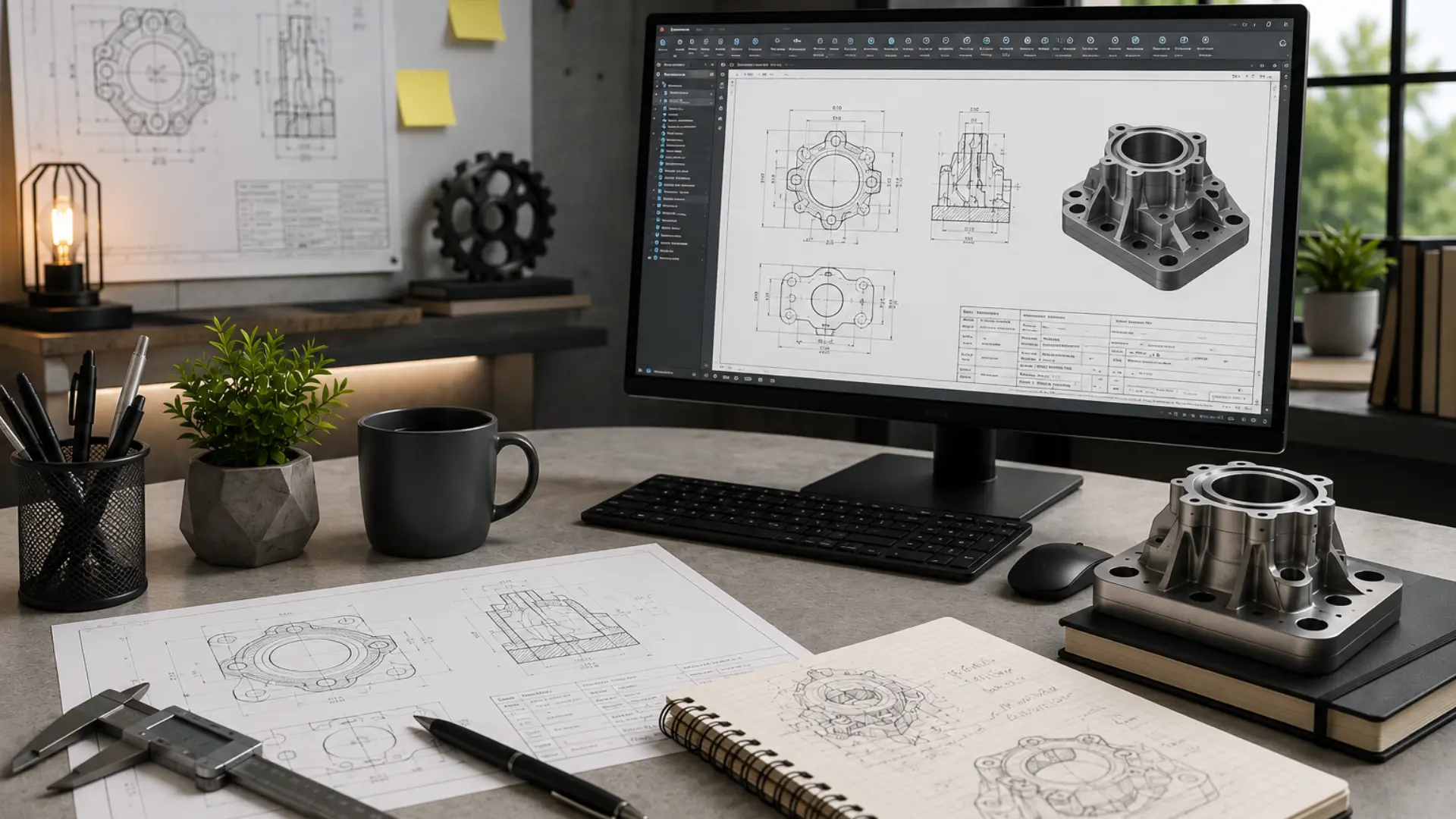
Every design team runs into the same wall at some point. Deadlines shrink, drawings pile up, and small errors turn into expensive delays. A reliable CAD Drafting Service fixes this problem at the root by giving teams accurate, ready-to-use drawings without the usual back and forth. Instead of chasing revisions or fixing mistakes late in the process, engineers and architects get clean, error-free files that move projects forward. This article looks at the most common design challenges companies face and how professional drafting support solves each one.


Why Design Challenges Slow Down Projects

Design problems rarely show up all at once. They creep in through small errors, missed details, or drawings that do not match the final build. A single wrong measurement can delay a project by weeks. Poor communication between departments can send a design in the wrong direction before anyone notices.

Most of these issues trace back to one root cause: drafting work that was rushed, handled by inexperienced staff, or done without the right software knowledge. Professional drafting teams solve this by bringing structure, consistency, and technical skill to every drawing they touch.

Design teams also feel pressure from tighter budgets and shorter timelines. Clients expect fast turnaround without sacrificing accuracy, and that combination is hard to deliver without dedicated drafting support. When drafting sits on the side desk of an already busy engineer, quality naturally drops. This happens not because the engineer lacks skill, but because drafting requires focused attention that a packed schedule rarely allows.

Inaccurate Measurements and Dimensioning Errors

Dimensioning mistakes cause more project delays than almost anything else. A missed decimal point or an incorrect tolerance can force an entire batch of parts to be scrapped. Manufacturing teams then lose time reordering materials and rescheduling production.

Skilled drafters check every dimension against design intent and manufacturing standards. They catch errors before drawings reach the shop floor, which protects both budget and schedule. This level of accuracy is hard to maintain in-house when staff juggle multiple projects at once.

The Cost of Small Errors

A single dimensioning error can ripple through an entire supply chain. Vendors quote based on drawings, so any inaccuracy leads to wrong material orders, wasted machining time, and frustrated clients. Professional drafters build in quality checks at every stage, so these errors get caught early instead of after production has already started.

Miscommunication Between Design and Engineering Teams

Design intent often gets lost between the person who sketches an idea and the engineer who has to build it. Sketches on a napkin or vague verbal instructions leave too much room for interpretation. When drawings are unclear, engineers guess, and guessing leads to rework.

A professional CAD drafting service closes this gap. Drafters translate rough concepts into precise, standardized drawings that both design and engineering teams can read the same way. Clear callouts, proper layering, and consistent formatting remove the guesswork, so everyone works from the same source of truth.

Slow and Inconsistent Manual Drafting

Manual drafting, or even basic in-house CAD work without dedicated specialists, tends to be slow. Drawings pile up because staff are pulled between design tasks, client meetings, and drafting duties. Deadlines slip, and quality suffers when people rush to catch up.

Outsourced drafting teams work faster because drafting is their only focus. They know the shortcuts, templates, and workflows that shave hours off every drawing set. This speed does not come at the cost of quality since experienced drafters still follow strict review processes before sending files back to the client.

Converting Rough Concepts into Precise 2D and 3D Models

Turning a rough sketch or an old paper drawing into a usable digital model is one of the toughest parts of any design project. Many companies still have legacy drawings from decades ago that need to be rebuilt from scratch. Doing this correctly requires both drafting skill and deep software knowledge.

This is where 2D Drafting in Solidworks becomes valuable. Solidworks allows drafters to build precise, editable 2D layouts that later feed into 3D modeling, simulation, and manufacturing workflows. A professional team can take a hand sketch, an outdated blueprint, or a rough concept and turn it into a fully dimensioned, production-ready drawing within days rather than weeks.

Legacy Drawing Conversion

Older companies often store decades of paper drawings or scanned PDFs with no editable source files. When a design needs updating, someone has to redraw it from scratch. Professional drafters specialize in this kind of conversion work. They rebuild legacy drawings into modern CAD formats while preserving original dimensions and design intent, so nothing gets lost in translation.

Maintaining Design Standards Across Multiple Projects

Companies that run several projects at once often struggle to keep drafting standards consistent. One project might use a different layer naming convention than another. Title blocks, line weights, and annotation styles can vary from drawing to drawing, which creates confusion when files move between teams or contractors.

A dedicated drafting service applies the same standards across every project. Templates, naming conventions, and quality checklists stay consistent no matter how many drawings pass through the pipeline. This consistency matters most when drawings need to be shared with outside vendors, contractors, or regulatory bodies that expect a certain format.

Scaling Drafting Work for Complex or Large Projects

Large projects generate huge volumes of drawings in short windows. An in-house team sized for normal workloads gets overwhelmed the moment a big project lands. Hiring temporary staff takes time, and training them on internal standards takes even longer.

Outsourced drafting teams scale up or down based on project needs. A company can send a large batch of drawings during a busy season and scale back once the workload normalizes. This flexibility saves money compared to maintaining a large in-house team year-round, and it keeps quality steady even when volume spikes.

Seasonal industries feel this benefit the most. Construction firms often see a surge of bids in spring, while manufacturers may face a rush of orders around new product launches. Building an in-house team large enough to handle peak demand means paying for idle capacity during slower months. A flexible drafting partner removes that trade-off entirely, since companies only pay for the work they actually need.

Choosing the Right Drafting Partner

Not every drafting provider delivers the same level of quality. Some outsource work to junior staff with little oversight, which brings back the same errors a company was trying to avoid. Others lack experience with specific industries, so drawings miss requirements that matter for manufacturing, construction, or compliance.

Before hiring a drafting partner, teams should ask a few direct questions. Does the provider have experience in the relevant industry? Do they offer revision support after delivery? Can they handle both new designs and legacy drawing conversions? A provider that answers yes to all three saves companies from switching vendors mid-project.

Software compatibility matters as well. A provider fluent in the same CAD platforms a company already uses avoids file conversion issues and keeps drawings editable on both ends. This small detail prevents a surprising number of headaches later in the project.

How Professional Drafting Solves These Problems Together

Each challenge listed above connects to the next. Poor communication leads to dimensioning errors. Inconsistent standards make legacy conversions harder. Slow manual processes make scaling nearly impossible. A professional drafting partner addresses all of these issues at once rather than patching them one at a time.

Experienced drafters bring standardized workflows, software expertise, and quality control checks that in-house teams often cannot maintain alongside their regular workload. The result is fewer errors, faster turnaround, and drawings that hold up through manufacturing, construction, or regulatory review.

Companies that adopt professional drafting support also free up their engineers and designers to focus on higher-value work. Instead of spending hours on repetitive drawing tasks, internal teams can concentrate on innovation, problem solving, and client relationships while drafting specialists handle the technical documentation.

Final Thoughts

Design challenges are a normal part of any project, but they do not have to slow things down. Dimensioning errors, miscommunication, slow manual work, inconsistent standards, and scaling problems all have one common solution: bringing in a team that specializes in drafting.

KEYWAY works with companies across industries to solve exactly these problems, combining technical drafting skill with fast turnaround and consistent quality. Whether a project needs legacy drawing conversion, precise 2D layouts, or full-scale drafting support for a complex build, the right partner makes the difference between a project that stalls and one that ships on time. For updates, project examples, and industry insights, follow along on LinkedIn.

How Roller Conveyor CAD Models Improve Material Handling Efficiency

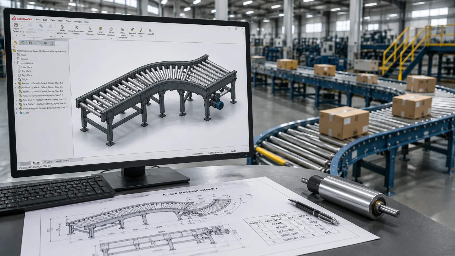
Material handling teams face constant pressure to move products faster and with fewer errors. A well designed Roller Conveyor CAD Model helps engineers solve this problem before a single part reaches the shop floor. It lets teams test layouts, spot clearance issues, and confirm load capacity long before installation begins. Companies that use accurate 3D models during planning often cut costly redesigns and shorten project timelines. This article looks at how these models work, why they matter, backs it with current industry data, and shows how they boost efficiency across a warehouse or production line.

What Is a Roller Conveyor CAD Model?

A Roller Conveyor CAD Model is a digital representation of a conveyor system built inside computer aided design software. Engineers use it to map out rollers, frames, motors, and support structures in exact detail. The model shows how each component fits together and how the full assembly will behave once installed.

Unlike a simple sketch, a CAD model carries real measurements, material properties, and mechanical tolerances. Teams can rotate the design, zoom into joints, and check how the conveyor interacts with nearby equipment. This level of detail helps prevent mistakes that often surface only after installation.

The Data: What Accurate Conveyor CAD Design Actually Delivers

The case for investing in detailed CAD and simulation work isn’t just intuition — it shows up clearly in reported project outcomes:

  • Optimizing conveyor layout to eliminate bottlenecks and transfer inefficiencies can boost overall throughput by 20–30% (Gough Econ).
  • Simulating conveyor behavior and validating designs before fabrication has been shown to reduce unplanned downtime by 30–60%, since most mechanical failures are predictable and preventable at the design stage rather than after installation.
  • Virtual commissioning — simulating servo axes, robot paths, and conveyor interference zones before fabrication — has been shown to cut commissioning time by 30–50% on industrial projects.
  • Coordinated 3D modeling and digital clash detection can cut rework by up to 40%, and resolving conflicts digitally instead of on-site has saved as much as 12% of total project cost on comparable builds.

At a glance:

MetricReported ImprovementSource
Throughput increase (layout optimization)20–30%Gough Econ
Unplanned downtime reduction30–60%Simulation/design validation studies
Commissioning time reduction30–50%Coordinated 3D modeling projects
Rework cost reductionUp to 40%Digital clash detection / 3D coordination

Why Material Handling Efficiency Depends on Accurate CAD Design

Every warehouse or distribution center runs on tight timing. Products need to move from receiving to storage to shipping without delays. A poorly planned conveyor line creates bottlenecks, damages goods, and slows down the entire operation.

Engineers rely on CAD design to catch these problems early. They can simulate product flow, check speed requirements, and confirm that rollers can handle expected loads. When the design is correct from the start, teams avoid the expensive trial and error that comes with physical prototypes.

Accurate models also support better communication. Plant managers, engineers, and equipment vendors can all view the same file and agree on specifications before manufacturing begins. This shared understanding reduces miscommunication and keeps projects on schedule.

Key Benefits of Using Roller Conveyor CAD Models

CAD modeling brings several practical advantages to material handling projects.

Faster Design Iterations

Engineers can adjust roller spacing, frame height, or motor placement within minutes. They do not need to rebuild a physical prototype for every change. This speed lets teams test multiple configurations and choose the most efficient one.

Better Space Planning

Warehouses often have limited floor space. A detailed model shows exactly how much room the conveyor needs, including clearance for maintenance access and other equipment. Planners avoid layout conflicts that would otherwise appear only after installation.

Reduced Manufacturing Errors

When a model includes precise dimensions and tolerances, manufacturers build parts that fit correctly the first time. Fewer errors mean fewer delays and lower rework costs.

Improved Load and Stress Analysis

Engineers can apply load simulations directly to the model. This shows whether the frame and rollers can support expected weight without bending or failing over time. Our related guide on how FEA analysis services reduce design failures and costs covers this process in more depth. Catching a weak point in the design phase costs far less than fixing it after installation.

Stronger Collaboration Across Teams

A shared 3D file gives everyone, from mechanical engineers to procurement teams, the same reference point. This clarity speeds up approvals and reduces the back and forth that paper drawings often create.

Planning a new conveyor line?

KEYWAY’s engineering team can build a manufacturing-ready roller conveyor model before you commit to installation. Explore our material handling design services to get started.

How Roller Conveyor CAD Models Streamline Design and Planning

A strong Roller Conveyor CAD workflow does more than just visualize a product. It connects design directly to manufacturing and installation. Engineers can export the model into formats that CNC machines or fabrication teams use, which removes the need for manual re-drawing.

The model also supports early testing of automation components, such as sensors, motors, and control systems. Teams can confirm that electrical and mechanical parts align correctly before ordering hardware. This step alone prevents many of the delays that mismatched components cause once teams find them on site.

Because the model is fully parametric, engineers can update one dimension and watch the entire assembly adjust automatically. This flexibility saves hours of manual redrawing and keeps every version of the design accurate and current.

Common Applications of Roller Conveyor CAD Models

Roller conveyor systems appear across many industries, and CAD models support each use case differently.

Warehousing and Distribution

Distribution centers use conveyor models to plan sortation lines, loading docks, and storage retrieval systems. Accurate models help these facilities handle high volumes without slowing down order fulfillment.

Manufacturing and Assembly Lines

Factories rely on conveyors to move parts between workstations. CAD models help engineers position each station correctly, so products flow smoothly from one process to the next.

Airport Baggage Handling

Airports need conveyor systems that operate reliably under constant use. Detailed models help planners design systems that handle heavy daily traffic while meeting strict safety codes.

Food and Beverage Processing

These facilities often require sanitary design standards. CAD models let engineers plan for easy cleaning access and corrosion resistant materials without compromising conveyor performance.

E-Commerce Fulfillment Centers

Online retailers depend on fast, accurate order processing. Conveyor models help these centers design flexible systems that can scale up during peak seasons without a full redesign of the facility.

Best Practices for Building a Roller Conveyor CAD Model

Engineers who follow a clear process get more value from their CAD work. A few practices consistently lead to better results.

Start With Accurate Load Data

Before drawing a single roller, gather real numbers on product weight, size, and throughput speed. Guesswork at this stage causes problems later. Accurate load data lets engineers size motors and frames correctly the first time.

Build in Maintenance Access

A conveyor that looks efficient on paper can still cause headaches if technicians cannot reach bearings, motors, or belts easily. Good models include clear access points from the very first draft, not as an afterthought.

Use Standard Components Where Possible

Custom parts drive up cost and lead time. Engineers who design around standard rollers, frames, and drive components keep budgets predictable and make future repairs simpler.

Validate the Model Against Real World Constraints

A model that looks perfect in software still needs to match the physical space it will occupy. Engineers should check ceiling height, column placement, and floor slope before finalizing any layout. Skipping this step often forces last minute redesigns during installation.

Keep the Model Updated Throughout the Project

Conveyor projects change as procurement, budget, or facility needs shift. Teams that keep their CAD file current avoid confusion between departments and prevent outdated versions from reaching the shop floor.

The Role of Simulation in Roller Conveyor CAD Design

Simulation adds another layer of value to the design process. Engineers can run virtual tests through KEYWAY’s simulation services that show how products move through the system under different speeds and volumes. This helps identify jam points, uneven loading, or spots where products might collide before any physical testing happens.

Simulation also supports better decision making around motor sizing and control logic. Teams can adjust variables like conveyor speed or spacing between products and immediately see the impact on throughput. Performing this kind of testing on a physical line would take much longer and cost far more, but it takes only minutes inside a CAD environment.

Facilities that combine simulation with detailed CAD models tend to launch new conveyor lines with fewer startup issues. Operators spend less time troubleshooting and more time running production at full capacity.

Choosing the Right CAD Partner for Conveyor Design

Not every design team has the in house resources to build detailed conveyor models. Many companies choose to work with a specialized partner instead. The right partner brings engineering expertise, familiarity with industry standards, and experience across multiple conveyor types.

KEYWAY works with material handling companies to build precise, manufacturing ready models that reduce design time and improve project outcomes. Their engineering team understands the mechanical and structural requirements that make a conveyor system both safe and efficient.

When evaluating a design partner, look for a team that communicates clearly, delivers models on schedule, and understands your specific industry requirements. A strong partnership shortens the path from concept to installation.

Final Thoughts

A detailed Roller Conveyor CAD Model gives engineering teams the confidence to design systems that work correctly the first time. It reduces errors, speeds up approvals, and helps facilities avoid the costly downtime that comes from poor planning. As material handling demands continue to grow, companies that invest in accurate CAD design will stay ahead of competitors still relying on guesswork and paper drawings. Sharing these insights on LinkedIn can also help engineering teams discover practical CAD solutions and industry expertise.

If your team is planning a new conveyor system or upgrading an existing line, working with an experienced design partner can make the process faster and far less stressful.

Best Ways to Optimize Machining with Advanced SolidWorks CAM Service

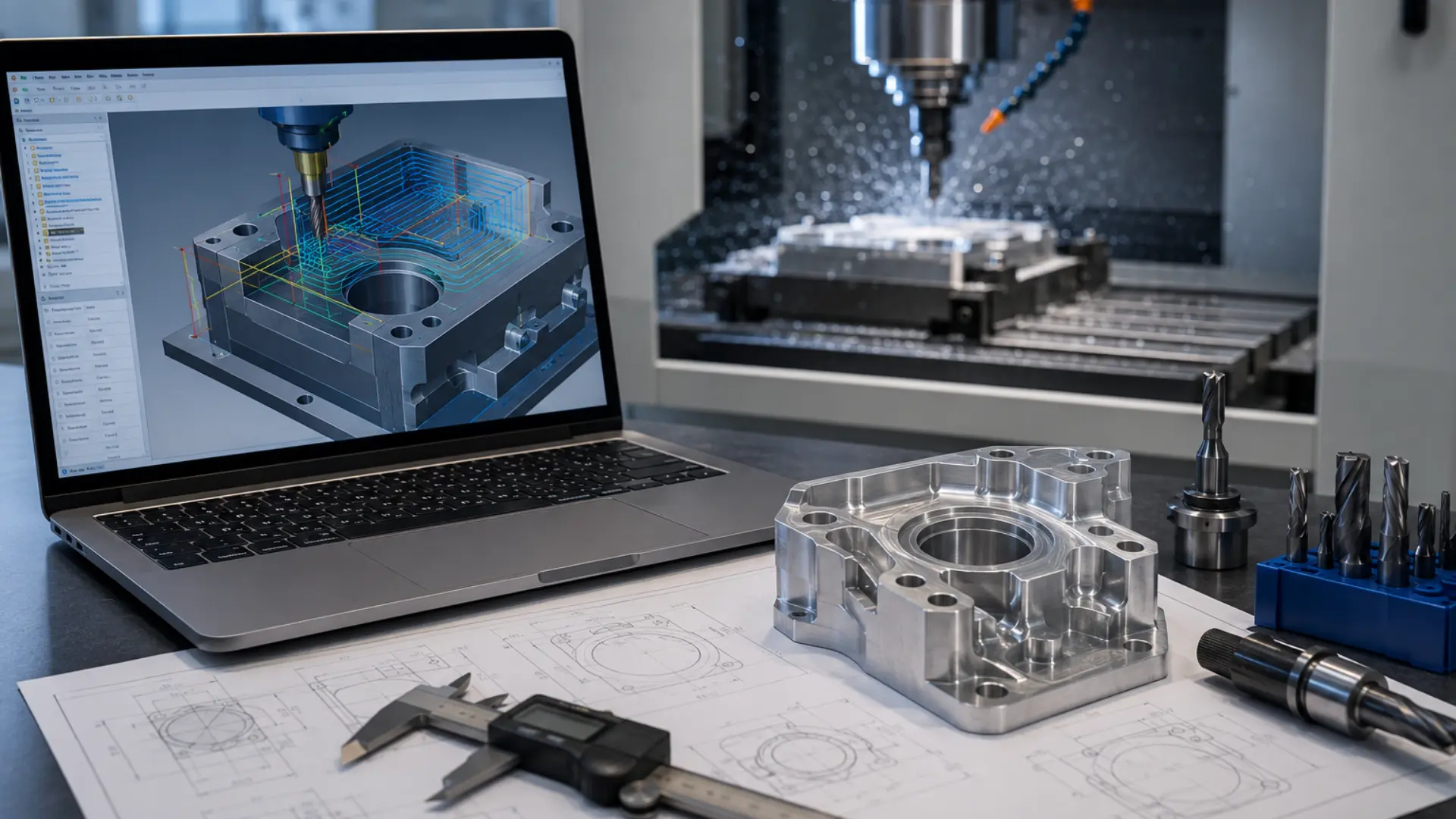
Manufacturing teams face constant pressure to cut costs, boost speed, and maintain top tier quality. That is exactly where a reliable SolidWorks CAM Service becomes valuable. This service connects design and production in one smooth workflow. Machinists spend less time troubleshooting and more time cutting parts correctly the first time. In this article, we walk through the best ways to optimize your machining process using advanced SolidWorks CAM tools, back it with current industry data, and explain why the right approach can transform your shop floor efficiency.

Why Machining Optimization Matters Today

Modern manufacturers cannot afford wasted material, idle machines, or long changeover times. Every minute a CNC machine sits without cutting costs money. Optimized machining reduces scrap, shortens lead times, and helps shops meet tighter delivery windows.

Companies that invest in smarter CAM programming often see fewer errors on the shop floor. They also spend less on rework. When toolpaths are planned correctly from the start, operators trust the program and run it with confidence.

The Data: What CAM Optimization Actually Delivers

Toolpath and simulation improvements aren’t just theoretical — shops that adopt smarter CAM programming report measurable gains across cycle time, tool life, and rework:

  • CNC optimization software can reduce cycle times by 25% to 70%, even on programs already generated by CAM systems, and can extend tool life by 100% or more by keeping chip thickness and cutter load constant (Modern Machine Shop).
  • High efficiency roughing strategies built into modern CAM systems can cut roughing cycle times by as much as 80% compared to traditional hogging passes, though total part cycle time gains depend on how much of the job is roughing versus finishing.
  • SolidCAM’s iMachining technology, one of the toolpath engines available inside SolidWorks-integrated CAM workflows, reports cycle time reductions of up to 70% on roughing operations and tool life extension of up to 5x.
  • A 2025 case review of a modern CAM stack found average cycle time down 35% on recurring parts, 70% fewer post-program manual edits, and a 20% reduction in rework linked directly to collision prevention in simulation.

At a glance:

MetricReported ImprovementSource
Roughing cycle time cutUp to 70%Modern Machine Shop / SolidCAM
Tool life extensionUp to 5x (100%+)Modern Machine Shop / SolidCAM
Manual post-program edits cut70%CAM Pro Software case study
Rework reduction (collision prevention)20%CAM Pro Software case study

Understanding SolidWorks CAM Service

SolidWorks CAM works directly inside the SolidWorks design environment. Engineers can generate toolpaths without exporting files to a separate CAM package. The software reads the 3D model’s features automatically, then recommends machining operations based on geometry. This tight integration cuts down on programming time and reduces the chance of errors that happen when data moves between separate systems.

A good CAM service does more than generate toolpaths. It fine tunes cutting parameters, selects the right tools for each operation, and verifies the program through simulation before it touches a machine. This step alone prevents costly mistakes like tool collisions or incorrect feed rates.

Key Ways to Optimize Machining with SolidWorks CAM

1. Streamline Toolpath Programming

Toolpath programming eats up a large chunk of a machinist’s day when done manually. SolidWorks CAM automates much of this work by recognizing features like holes, pockets, and slots directly from the CAD model. The software then suggests appropriate machining strategies for each feature. This automation saves hours on complex parts and reduces the risk of human error during setup.

2. Reduce Cycle Time with Smart Simulation

Simulation lets you preview the entire machining process before cutting a single chip. You can spot collisions, check tool clearance, and confirm that feed rates match the material you are cutting. Catching these issues early helps you avoid downtime on the shop floor. Shops that run simulations consistently report shorter cycle times and fewer scrapped parts.

3. Improve Accuracy with Integrated Design Data

SolidWorks CAM pulls data straight from the CAD model, so there is no gap between design intent and machining output. Engineers update the model, and the CAM program updates automatically. This keeps tolerances tight and prevents outdated toolpaths from entering production. Precision improves because the numbers driving the machine come from the same source as the design.

4. Cut Material Waste Through Better Planning

Smart nesting and stock management features help planners use raw material more efficiently. The software calculates material needs based on actual part geometry instead of rough estimates. Our related guide on how CAMWorks nesting improves material utilization breaks this down in more depth. This reduces scrap and keeps material costs under control, which matters even more when you work with expensive alloys.

5. Strengthen Collaboration Between Design and Manufacturing

Design and manufacturing teams often work in silos, and that gap causes delays. Pairing CAM programming with accurate Solidworks Drafting keeps everyone on the same page, from the first sketch to the final cut part. Clear drawings paired with automated toolpaths mean fewer questions on the shop floor and faster approvals. When design and manufacturing speak the same language, projects move through production faster.

Want to see how much cycle time you could cut?

KEYWAY’s team can review a sample part and show you where SolidWorks CAM would save the most time. Explore our CAM services to get started.

How SolidWorks CAM Fits into a Modern Machine Shop

A machine shop runs on tight schedules. Parts move from design review to programming to the machine floor within days, sometimes hours. SolidWorks CAM fits into this pace because it lives inside the same software engineers already use to build the model. Programmers do not need to relearn a new interface or wait for a file to translate correctly.

This matters most when a design changes late in the process. A client might request a different hole pattern or a tighter tolerance the day before production starts. Because the CAM data stays linked to the model, a quick edit updates the toolpath automatically. The programmer reviews the change, reruns the simulation, and sends the job to the machine without starting from scratch.

Choosing the Right CAM Strategy for Your Project

Not every part needs the same machining approach. Picking the right strategy up front saves time and protects your tools from unnecessary wear. SolidWorks CAM supports several strategies, and understanding when to use each one makes a real difference in shop performance.

Milling for Complex Geometry

Milling handles parts with pockets, contours, and multiple faces. SolidWorks CAM recognizes these features and applies roughing and finishing passes automatically. Programmers can still adjust stepover, depth of cut, and tool selection whenever a part calls for extra care.

Turning for Cylindrical Parts

Turning suits shafts, bushings, and other round components. The software calculates efficient cutting sequences that reduce tool changes and keep spindle time low. Shops that machine a high volume of cylindrical parts often see the biggest time savings here.

Multi-Axis Machining for Advanced Parts

Aerospace and medical parts often need five-axis machining to reach every surface in one setup. SolidWorks CAM supports these advanced strategies, which cuts down on repositioning and improves accuracy across the whole part.

Tips for Getting Started with SolidWorks CAM

Shops moving to SolidWorks CAM for the first time do not need to overhaul their entire process overnight. A gradual rollout tends to work best and keeps the whole team on board.

  • Start with simple parts to build confidence in the toolpaths
  • Train one or two programmers first, then expand knowledge across the team
  • Use the built-in feature recognition before writing custom toolpaths manually
  • Run every new program through simulation, even for parts you know well
  • Review post-processor settings so output matches your specific machine controller

Following these steps helps a shop avoid the common frustration of adopting new software too quickly. Small wins early on build trust in the system, and that trust carries over as programmers tackle more complex parts.

Benefits of Partnering with Experts for CAM Services

Not every shop has the bandwidth to train staff on advanced CAM features. Partnering with a dedicated service provider gives you access to specialists who already know how to get the most performance out of SolidWorks CAM. This partnership brings several advantages:

  • Faster programming turnaround for complex parts
  • Reduced tool wear through optimized cutting parameters
  • Fewer machine collisions thanks to thorough simulation checks
  • Consistent quality across multiple production runs
  • Lower overall machining costs over time

Outsourcing CAM programming also frees up your in-house engineers, so they can focus on design work instead of spending hours fine tuning toolpaths.

Common Challenges in Machining Optimization

Even with the best tools, shops run into obstacles. Outdated machine tools may not support advanced toolpath strategies. Some teams stick to manual programming out of habit, even when automated tools would save time. Training gaps create another common issue, since not every machinist gets exposure to the latest CAM features.

Addressing these challenges usually starts with a clear evaluation of current workflows. Shops that adopt new tools gradually, rather than all at once, tend to see smoother transitions and better buy-in from their teams.

Measuring the Return on CAM Optimization

Shop owners want proof that a new tool actually pays off. Tracking a few key metrics before and after adopting SolidWorks CAM makes the return on investment easy to see. Cycle time per part, scrap rate, and programming hours per job all tend to improve within the first few months.

Tool life often improves too, since simulation catches feed and speed issues before they damage a cutter. Over a full year, these small gains add up to real savings on both material and labor costs. Shops that review these numbers quarterly can spot trends early and adjust their programming approach before small issues turn into bigger costs.

Where SolidWorks CAM Delivers the Most Value

Certain industries see faster payback from SolidWorks CAM than others. Aerospace and medical device shops benefit from the tight tolerances and repeatable simulation checks the software offers. Automotive suppliers gain from shorter cycle times on high-volume runs, where even small efficiency gains multiply across thousands of parts.

Job shops that handle a wide mix of parts also benefit, since feature recognition speeds up programming on one-off jobs that would otherwise take hours to set up manually. Regardless of industry, the common thread is a workflow that connects design and machining without unnecessary delays.

Final Thoughts

Optimizing your machining process with SolidWorks CAM is not a one-time fix. It is an ongoing effort that combines smart programming, accurate simulation, and strong collaboration between design and manufacturing teams. Shops that commit to this approach see fewer errors, shorter cycle times, and lower costs over the long run.

If you are ready to take your machining process to the next level, KEYWAY offers the expertise and tools to help you get there. Their team knows how to turn a good CAD model into an efficient, reliable production run.

Why Businesses Need Product Rendering Service for Faster Approvals

Every product team knows the pain of waiting on approvals. A new packaging design sits in someone’s inbox for days. A sales deck needs updated visuals before a client meeting. A manufacturer wants to see the final look before signing off on production. This is exactly where a Product Rendering Service changes the game. Instead of waiting weeks for physical samples or rough sketches, businesses can now generate photorealistic visuals in days, sometimes hours, and get stakeholders to say yes much faster.

In this article, we’ll break down why rendering has become a must-have tool for modern brands, back it with current industry data, and cover what to look for when choosing a rendering partner.

The Approval Bottleneck Every Brand Faces

Approvals slow everything down. A packaging redesign might pass through marketing, then legal, then a retail partner, then the client. Each step adds days or weeks to the timeline. Traditional methods make this worse because teams often rely on flat mockups or physical prototypes that cost money and time to produce.

Physical samples create their own problems too. If a stakeholder wants to see three color variations, a team has to produce three separate prototypes. That means more material costs, more shipping delays, and more waiting. By the time samples arrive, market trends may have already shifted.

This is why more companies are turning toward digital solutions. Rendering removes the physical production step entirely from the early approval stages. Teams can generate multiple versions of a design within the same day and share them instantly with decision-makers anywhere in the world.

The Data: What Rendering Actually Delivers

The shift toward digital visualization isn’t just a trend – it shows up clearly in market growth and in reported business outcomes. Here’s what the numbers say:

  • The global 3D rendering market was valued at roughly $4.85 billion in 2025 and is projected to keep climbing at a double-digit annual growth rate through the early 2030s, as more industries move approvals and design reviews into digital-first workflows (Grand View Research).
  • Businesses switching from traditional photography and physical prototyping to 3D rendering have reported cutting production costs by up to 70%, while some high-value product categories saw conversion-rate increases of up to 94% (3Devision ROI Report).
  • Furniture retailer Riverside Furniture saved roughly $100,000 annually by replacing physical photoshoots with rendering, and EQ3 saw a 36% increase in conversions and an 88% lift in average order value after adopting 3D visualization (Cylindo case study).
  • Return rates tied to “product didn’t look like the photo” complaints have dropped by 30–40% for brands using realistic 3D visuals instead of flat images, directly reducing the cost of post-sale disputes and reshoots.

What Is Product Rendering and Why It Matters

Product rendering is the process of creating a photorealistic digital image of a product using 3D software. Designers build a digital model, then apply lighting, textures, and materials to make it look exactly like the real thing – sometimes even better than a photograph.

Businesses use Product Design Renders for many purposes. Marketing teams use them for ad campaigns before the product exists. Sales teams use them to pitch new lines to retailers. Manufacturing teams use them to confirm design specifications before committing to tooling and molds.

The biggest advantage is speed. A rendering studio can turn around multiple design iterations in the time it takes to produce a single physical sample. This directly shortens the approval cycle because stakeholders see accurate visuals right away instead of waiting for a physical version.

How Rendering Speeds Up the Approval Process

Faster approvals happen because rendering removes several traditional bottlenecks:

  • No physical production delays: Teams skip the manufacturing step for early reviews, so there is nothing to ship or wait on.
  • Instant revisions: Designers can adjust colors, materials, or angles in the same file and send updates within hours.
  • Multiple options at once: Stakeholders can compare five versions side by side instead of approving one option at a time.
  • Remote collaboration: Teams across different countries can review the same high-resolution image without needing to meet in person.
  • Clear visual accuracy: Realistic renders reduce the back-and-forth that happens when a sketch or 2D mockup leaves too much to interpretation.

When companies work with an experienced Product Rendering Service, they often see approval timelines drop from weeks to just a few days. This matters most for brands that operate on tight retail calendars or seasonal launch windows.

Tired of approval cycles that drag on for weeks?

See how KEYWAY’s rendering team can help you move from concept to sign-off in days. Book a free consultation and get a turnaround estimate for your next project.

Cost Savings That Go Beyond Speed

Speed grabs the headlines, but the cost savings deserve equal attention. Producing physical prototypes for every design variation adds up quickly. Materials, labor, shipping, and storage all cost money, and none of that spend happens until the design is locked.

Rendering flips this model. A design team builds one digital asset, then explores color options, packaging formats, or material finishes without touching a factory floor. If a stakeholder rejects a design direction, nothing physical gets wasted. The team simply adjusts the digital file and resubmits it for review.

This approach also protects budgets during the early concept phase, when ideas change often. Instead of locking in a direction too early just to save on prototype costs, brands can explore more creative options because each variation costs far less to produce digitally than physically.

Building Stronger Client and Stakeholder Trust

Approvals move faster when decision-makers trust what they are looking at. Grainy sketches or basic 3D wireframes leave too much room for guesswork. A photorealistic render shows exactly how a product will look under real lighting conditions, on a shelf, or in a customer’s hand.

This level of detail builds confidence among stakeholders because they are not approving an idea – they are approving something that looks finished. Retail buyers, for example, want to see how a product will sit on their shelves before committing to an order. A high-quality render answers that question immediately, without needing a physical sample shipped to their office.

Brands like KEYWAY have built their reputation around this exact need, helping companies visualize products with enough accuracy that stakeholders can make confident decisions on the first review instead of requesting round after round of revisions.

Where Rendering Fits Across Different Industries

Rendering is not limited to one type of business. Several industries rely on it heavily for faster approvals and stronger presentations.

Consumer packaged goods brands use rendering to test packaging designs before committing to print runs. This helps them react quickly to market trends without wasting materials on designs that might not perform well.

Furniture and home goods companies use rendering to show customers new collections before the items are manufactured. This lets them gauge interest and secure retail orders ahead of production.

Electronics manufacturers use rendering to present new device concepts to investors or partners long before a working prototype exists. This speeds up funding decisions and partnership agreements.

Cosmetics and beauty brands use rendering to test bottle shapes, labels, and finishes across many variations quickly, which matters in an industry known for fast trend cycles.

Across every one of these industries, the core benefit stays the same. Teams see accurate visuals sooner, which means they approve designs sooner, which means products reach the market faster.

If you want a deeper look at how photorealistic visuals help teams present concepts more effectively, our related guide, Struggling with Design Presentation? Try Photorealistic Rendering Services, walks through the presentation side of this in more detail.

Choosing the Right Rendering Partner

Not every rendering studio delivers the same quality or turnaround time. Businesses should look at a few key factors before choosing a partner.

Experience With Your Product Category

A studio that specializes in packaging renders may not have the same expertise in furniture or electronics. Ask to see previous work in your specific category before signing on.

Turnaround Time

Since faster approvals are the main goal, confirm how quickly the studio can deliver first drafts and revisions. Some studios promise fast timelines but struggle to hit them once a project starts.

Revision Process

Find out how the studio handles feedback. A smooth revision process, where changes get made quickly and clearly, prevents the approval cycle from getting stuck in endless back-and-forth.

Communication and File Formats

Make sure the studio can deliver files in the formats your marketing, sales, and manufacturing teams actually need, whether that is high-resolution stills, 360-degree spins, or files ready for animation.

Common Mistakes Businesses Make With Rendering

Even with a great rendering partner, some businesses slow themselves down through avoidable mistakes.

One common issue is unclear briefs. If a team does not provide clear reference materials, dimensions, or brand guidelines upfront, the studio has to guess, and that guesswork leads to more revision rounds.

Another mistake is skipping internal alignment before sending files for review. If marketing, sales, and leadership have not agreed on the direction internally, the rendering studio ends up caught between conflicting feedback, which stretches out the timeline instead of shortening it.

Finally, some companies treat rendering as a one-time need instead of an ongoing tool. Brands that build rendering into their regular design workflow, rather than using it only for big launches, tend to see faster approvals across the board because their teams and stakeholders become used to reviewing digital assets quickly.

Conclusion

Faster approvals are not just a nice bonus – they directly affect how quickly a business can launch products, respond to trends, and win over retail partners. A skilled Product Rendering Service removes the slow, costly steps of traditional prototyping and replaces them with accurate, shareable visuals that stakeholders can approve with confidence.

Businesses that invest in strong rendering partnerships, such as working with a team like KEYWAY, often find that their entire product development timeline shortens, not just the approval stage. When design, marketing, and manufacturing teams all work from the same realistic visuals, everyone moves faster and with fewer surprises along the way.

Complete Guide to Mechanical Design Services and Mechanical Reverse Engineering for Modern Product Development

Today, the industries are dynamic, and the businesses that are businesses are always being pushed to produce efficient, innovative, and cost-effective products. Advanced engineering solutions are essential for companies to remain competitive across fields such as Automotive, Aerospace, Industrial Equipment, and Consumer Products. This is where Mechanical Design Services play a crucial role in helping manufacturers and product developers create high-performance products with improved accuracy and reduced development time.

Meanwhile, many businesses also rely on Mechanical Reverse Engineering to upgrade their existing products, recreate obsolete parts, and enhance their product performance without building from the ground up. These engineering solutions are combined to create the bedrock of today’s product development and manufacturing. In this guide, we will explore how these services work, their benefits, applications, and why they are essential for businesses aiming to achieve innovation and efficiency.

What Are Mechanical Design Services?

These services involve planning, designing, modelling, and optimizing mechanical systems, products, and components using advanced engineering tools and software. The services they offer assist businesses in transforming concepts into goods that can be manufactured, along with making sure that they are practical, durable, and economical.

Advanced CAD and simulation software – mechanical design engineers apply engineering analysis to develop detailed designs that focus on technical and operational requirements. The process emphasizes the product function, manufacturability, material selection, and standard consideration.

These services are commonly used for:

  • Product design and development
  • Sheet metal design
  • Machine design
  • Industrial equipment design
  • 3D modelling and drafting
  • CAD conversion and detailing
  • Prototype development
  • Design optimization

Professional engineering assistance could benefit any company that is building a fresh product or updating an older product, significantly reducing downtime and errors throughout the development process.

Importance of Mechanical Design in Modern Product Development

Today, it’s not just about the idea of the product; it’s about development. Products should be useful, dependable, economical, and easy to produce. That’s where engineering-driven design is important.

Here are some major advantages of using professional mechanical design solutions:

Improved Product Accuracy

With engineering software, designers can design high-accuracy models and assemblies. It ensures dimensional accuracy and enhances the quality of the product.

Faster Development Process

Digital modelling and simulation enable engineers to recognize potential problem areas early in the design process, avoiding costly redesigns and delays.

Cost Optimization

Proper design planning helps businesses reduce material waste, optimize manufacturing processes, and lower production costs.

Better Product Performance

Optimizing the design for engineering analysis to increase durability, functionality, and efficiency.

Easy Collaboration

Modern CAD systems allow multiple teams to collaborate smoothly during product development.

Understanding Mechanical Reverse Engineering

Mechanical Reverse Engineering is the analysis of an existing product, component, or machine to determine its design, specifications, and functions. Using advanced scanning technologies, CAD tools, and measurement techniques, engineers create digital models of physical components.

This method is particularly helpful if original design sheets, technical drawings, or CAD data are not available.

Reverse engineering is commonly used for:

  • Recreating obsolete parts
  • Product redesign and improvement
  • Competitor product analysis
  • Repair and maintenance solutions
  • Legacy equipment modernization
  • Manufacturing documentation
  • Quality inspection & validation

Companies across various industries use reverse engineering to save time, reduce development costs, and improve existing products.

How Mechanical Reverse Engineering Works?

The first step engineers take is to examine the physical piece and take dimensional measurements with the following tools:

  • 3D scanners
  • Coordinate Measuring Machines (CMM)
  • Laser scanners
  • Digital calipers & measuring devices
  • 3D Modelling

Using engineering software, the data collected is then transformed into precise 3D CAD models.

Design Analysis

Engineers examine materials characteristics, assembly structure, tolerances, and product function.

Design Optimization

Existing designs can be improved to enhance performance, reduce weight, or simplify manufacturing.

Documentation and Manufacturing Support

Final engineering drawings and CAD are created for manufacturing and future changes.

Applications of Mechanical Design and Reverse Engineering

Both engineering solutions are widely used across industries for product innovation and operational efficiency.

Automotive Industry

Engineering services are used by automotive manufacturers to propose enhancements to engine systems, transmission parts, vehicle components, and for performance improvements.

Aerospace Industry

Precision engineering is essential in aerospace applications where accuracy and reliability are critical.

Industrial Manufacturing

Reverse engineering is used in the manufacturing sector to replace obsolete components within a machine or plant and enhance efficiencies.

Medical Equipment

Precision parts and the creation of custom equipment are methods of advanced engineering used by medical device manufacturers.

Consumer Products

Design engineering is a process used in product companies to develop innovative, functional products.

Benefits of Combining Design and Reverse Engineering

Design engineering and reverse engineering are frequently integrated to enhance efficiency and innovation within businesses.

Faster Product Upgrades

Although the existing product is not expensive to carry out the task as quickly as possible without the need to use another new system.

Reduced Development Costs

Using existing design ideas reduces research and development costs.

Improved Product Quality 

Businesses can use engineering analysis to pinpoint design flaws and enhance the performance of their products.

Better Manufacturing Efficiency

Optimized designs simplify the production process and enhance manufacturability.

Preservation of Legacy Systems

Restoration of older machinery and components is possible even where documentation is not available.

Role of CAD and Advanced Technologies

Advanced software and digital technologies are crucial to modern engineering. CAD software, simulation tools, and 3D scanning technologies have revolutionized the way products are designed and analyzed.

Examples of commonly used technologies:

  • CAD software for 3D Modelling and Drafting
  • CAE simulation and analysis tools
  • Finite Element Analysis (FEA)
  • Computational Fluid Dynamics (CFD)
  • 3D laser scanning
  • Rapid prototyping and 3D printing

These technologies help to increase design accuracy, minimise development risks, and facilitate team collaboration.

Choosing the Right Engineering Partner

Choosing the appropriate engineering service provider is a key factor in project success. Businesses should look for companies with:

  • Industry experience.
  • Skilled engineering teams.
  • Proficiency in CAD and simulation software.
  • Quality assurance processes.
  • Effective project management skills.
  • Ability to provide customized solutions.

A reliable engineering partner can help streamline product development, reduce turnaround time, and ensure high-quality deliverables.

Conclusion

Modern product development requires precision and innovation. Mechanical Design Services improve product quality, reduce development time, and optimize manufacturing processes. Mechanical Reverse Engineering helps recreate components, improve designs, and enhance performance. Together, these engineering solutions help businesses remain competitive and efficient in evolving industries.

Keyways provides engineering solutions for product development and manufacturing industries. Connect with Keyways on LinkedIn to explore their latest engineering insights and industry updates.

How CAMWorks Nesting Enhances Material Utilization in CAM Outsourcing Services?

In the current manufacturing landscape, companies are always looking for opportunities to minimise waste, increase efficiency, and optimise costs. Waste is a major concern in fabrication and CNC machining manufacturing, particularly when using high-cost materials. To reduce these inefficiencies, manufacturers often turn to CAM Outsourcing Services for increased productivity and to streamline production.

One such solution, widely used in today’s manufacturing environment, enables manufacturers to optimise material usage by nesting parts on sheets. This process maximises material usage, optimises cutting operations, and drives productivity.

Understanding CAMWorks Nesting in Manufacturing

Nesting is a process in manufacturing where parts are placed on a material in the most optimal arrangement. This process optimises the use of raw material and reduces wastage of material.

Key advantages of nesting technology include:

  • Better material utilization
  • Reduced production waste
  • Faster cutting operations
  • Improved manufacturing efficiency
  • Optimized sheet layouts

Manufacturers can achieve efficient sheet layouts by applying smart algorithms that minimise waste and ensure production accuracy.

Improved Material Utilization

Minimising waste is crucial for cost reduction. Inefficient layouts result in wasted space, which increases waste and costs.

CAMworks Nesting software allows companies to improve their sheet layouts by arranging parts in the most efficient way. This ensures that companies get the most out of each sheet of material and produce the least amount of waste.

Benefits of optimized material usage:

  • Reduced raw material waste.
  • Lower production costs.
  • Better sheet utilization.
  • Increased profitability.

This is particularly important in sectors that work with expensive materials like aluminum, steel, composites, and wood.

Faster Production and Workflow Efficiency

Production time is a critical factor in meeting work schedules and client demands. Traditional nesting techniques can be slow and inefficient, particularly when dealing with complex projects.

Automated nesting improves efficiency by:

  • Minimising manual layout design.
  • Accelerating production preparation.
  • Improving cutting efficiency.
  • Streamlining machining workflows.

Automated nesting systems allow manufacturers to create efficient layouts in a short time, increasing productivity and cutting programming time.

Reduced Scrap and Operational Costs

Waste has a direct impact on the bottom line. Every unused portion of material increases operational costs and reduces production efficiency.

Cost-saving advantages include:

  • Lower scrap generation
  • Reduced material expenses
  • Better resource optimization
  • Improved operational efficiency

Through better resource optimization, manufacturers can save money and improve profitability in the long term.

Better Accuracy and Consistency

Precision is critical in CNC machining and fabrication. Human nesting can lead to positioning inconsistencies and cutting mistakes.

Automated nesting helps improve:

  • Layout accuracy
  • Consistent part placement
  • Precision cutting alignment
  • Reduced human errors

Using improved nesting techniques, manufacturers can achieve consistent quality in their production while avoiding errors in fabrication.

Enhanced Flexibility for Complex Projects

Contemporary manufacturing projects may include complex part shapes, multiple materials, and sheet sizes. These complexities can lead to longer production times and waste.

Advanced nesting systems support:

  • Multiple material types
  • Different sheet dimensions
  • Complex part designs
  • Batch production optimization

This capability enables manufacturers to accommodate a variety of production needs while ensuring productivity.

Increased Productivity Through Automation

Automation is a key driver of productivity gains in manufacturing. Automation removes manual steps, manufacturers can concentrate on more important tasks, and boost productivity.

Productivity benefits include:

  • Faster nesting generation
  • Reduced manual intervention
  • Improved machine utilization
  • Higher production output

CAMworks Nesting helps manufacturers with a faster and more efficient production process by automating the creation of layouts and enhancing productivity in various machining operations.

How CAM Outsourcing Services Support Manufacturers?

CAM Outsourcing Services is a popular choice for companies seeking access to expert knowledge and cutting-edge manufacturing technology without the need for significant investment in in-house capabilities.

Key outsourcing benefits include:

  • Access to experienced professionals
  • Reduced operational expenses
  • Faster project completion
  • Improved workflow efficiency
  • Scalable production support

Outsourcing also helps companies concentrate on their key activities while leaving programming, nesting, and production planning to the experts.

Supporting Sustainable Manufacturing Practices

Sustainability is a growing trend in manufacturing. Minimising waste reduces costs and contributes to a more sustainable approach to manufacturing.

Sustainable manufacturing benefits include: 

  • Lower material consumption.
  • Reduced production waste.
  • Improved resource efficiency.
  • Better environmental performance.

Efficient nesting strategies help manufacturers minimize scrap and contribute to more sustainable manufacturing operations.

Competitive Advantage in Manufacturing

Manufacturers that increase efficiency and decrease waste have a greater competitive advantage. Increasing production efficiency allows companies to complete projects on time and on budget.

Competitive advantages include:

  • Improved production efficiency
  • Reduced manufacturing costs
  • Faster delivery timelines
  • Better product consistency

The combination of cutting-edge nesting systems and workflows can help manufacturers boost their profitability without compromising quality.

Improved Production Planning and Resource Management

The production process requires effective planning because it ensures operational efficiency and project completion within scheduled time frames. When planning fails to meet requirements, it produces material shortages and machine breakdowns, which result in production delays that decrease total work productivity.

Advanced nesting solutions help improve production planning by: 

  • Optimizing material allocation
  • Improving machine scheduling
  • Reducing production bottlenecks
  • Enhancing workflow coordination

Intelligent nesting systems enable businesses to optimize resource management while enhancing operational efficiency and maintaining steady production output throughout various projects.

Conclusion

Optimizing material usage is a key factor in increasing productivity and lowering costs. CAMworks Nesting enables businesses to maximise material efficiency, minimise waste, and enhance productivity. Enhanced material efficiency and process integration can lead to improved productivity and profitability.

Keyways offers cutting-edge manufacturing and engineering technologies that enhance productivity, minimize waste, and streamline processes. Follow Keyways on LinkedIn for better manufacturing solutions to grow your business.