
Material handling teams face constant pressure to move products faster and with fewer errors. A well designed Roller Conveyor CAD Model helps engineers solve this problem before a single part reaches the shop floor. It lets teams test layouts, spot clearance issues, and confirm load capacity long before installation begins. Companies that use accurate 3D models during planning often cut costly redesigns and shorten project timelines. This article looks at how these models work, why they matter, backs it with current industry data, and shows how they boost efficiency across a warehouse or production line.
What Is a Roller Conveyor CAD Model?
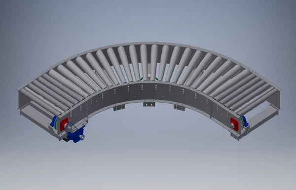
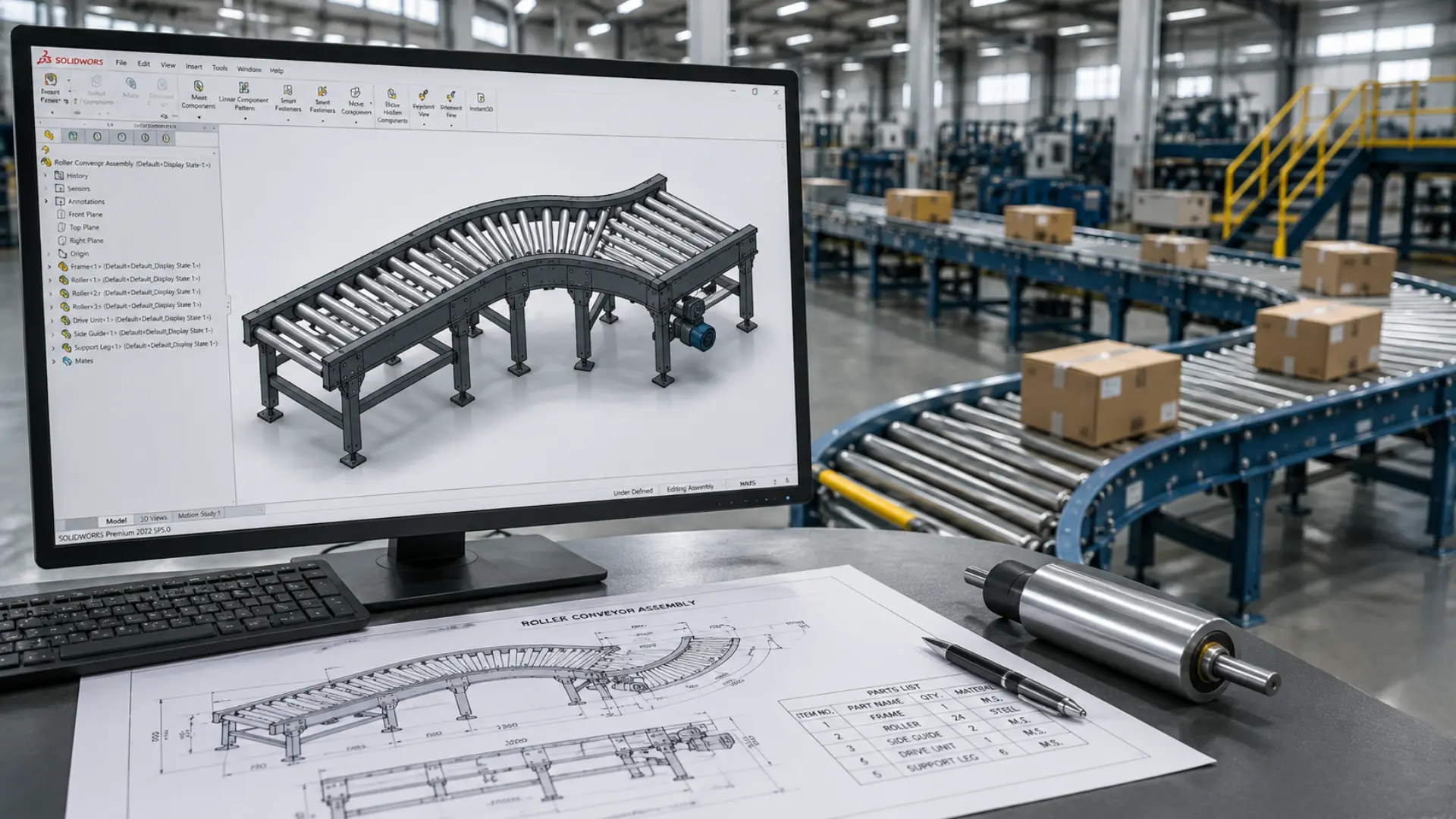
A Roller Conveyor CAD Model is a digital representation of a conveyor system built inside computer aided design software. Engineers use it to map out rollers, frames, motors, and support structures in exact detail. The model shows how each component fits together and how the full assembly will behave once installed.
Unlike a simple sketch, a CAD model carries real measurements, material properties, and mechanical tolerances. Teams can rotate the design, zoom into joints, and check how the conveyor interacts with nearby equipment. This level of detail helps prevent mistakes that often surface only after installation.
The Data: What Accurate Conveyor CAD Design Actually Delivers
The case for investing in detailed CAD and simulation work isn’t just intuition — it shows up clearly in reported project outcomes:
- Optimizing conveyor layout to eliminate bottlenecks and transfer inefficiencies can boost overall throughput by 20–30% (Gough Econ).
- Simulating conveyor behavior and validating designs before fabrication has been shown to reduce unplanned downtime by 30–60%, since most mechanical failures are predictable and preventable at the design stage rather than after installation.
- Virtual commissioning — simulating servo axes, robot paths, and conveyor interference zones before fabrication — has been shown to cut commissioning time by 30–50% on industrial projects.
- Coordinated 3D modeling and digital clash detection can cut rework by up to 40%, and resolving conflicts digitally instead of on-site has saved as much as 12% of total project cost on comparable builds.
At a glance:
| Metric | Reported Improvement | Source |
| Throughput increase (layout optimization) | 20–30% | Gough Econ |
| Unplanned downtime reduction | 30–60% | Simulation/design validation studies |
| Commissioning time reduction | 30–50% | Coordinated 3D modeling projects |
| Rework cost reduction | Up to 40% | Digital clash detection / 3D coordination |
Why Material Handling Efficiency Depends on Accurate CAD Design
Every warehouse or distribution center runs on tight timing. Products need to move from receiving to storage to shipping without delays. A poorly planned conveyor line creates bottlenecks, damages goods, and slows down the entire operation.
Engineers rely on CAD design to catch these problems early. They can simulate product flow, check speed requirements, and confirm that rollers can handle expected loads. When the design is correct from the start, teams avoid the expensive trial and error that comes with physical prototypes.
Accurate models also support better communication. Plant managers, engineers, and equipment vendors can all view the same file and agree on specifications before manufacturing begins. This shared understanding reduces miscommunication and keeps projects on schedule.
Key Benefits of Using Roller Conveyor CAD Models
CAD modeling brings several practical advantages to material handling projects.
Faster Design Iterations
Engineers can adjust roller spacing, frame height, or motor placement within minutes. They do not need to rebuild a physical prototype for every change. This speed lets teams test multiple configurations and choose the most efficient one.
Better Space Planning
Warehouses often have limited floor space. A detailed model shows exactly how much room the conveyor needs, including clearance for maintenance access and other equipment. Planners avoid layout conflicts that would otherwise appear only after installation.
Reduced Manufacturing Errors
When a model includes precise dimensions and tolerances, manufacturers build parts that fit correctly the first time. Fewer errors mean fewer delays and lower rework costs.
Improved Load and Stress Analysis
Engineers can apply load simulations directly to the model. This shows whether the frame and rollers can support expected weight without bending or failing over time. Our related guide on how FEA analysis services reduce design failures and costs covers this process in more depth. Catching a weak point in the design phase costs far less than fixing it after installation.
Stronger Collaboration Across Teams
A shared 3D file gives everyone, from mechanical engineers to procurement teams, the same reference point. This clarity speeds up approvals and reduces the back and forth that paper drawings often create.
| Planning a new conveyor line? KEYWAY’s engineering team can build a manufacturing-ready roller conveyor model before you commit to installation. Explore our material handling design services to get started. |
How Roller Conveyor CAD Models Streamline Design and Planning
A strong Roller Conveyor CAD workflow does more than just visualize a product. It connects design directly to manufacturing and installation. Engineers can export the model into formats that CNC machines or fabrication teams use, which removes the need for manual re-drawing.
The model also supports early testing of automation components, such as sensors, motors, and control systems. Teams can confirm that electrical and mechanical parts align correctly before ordering hardware. This step alone prevents many of the delays that mismatched components cause once teams find them on site.
Because the model is fully parametric, engineers can update one dimension and watch the entire assembly adjust automatically. This flexibility saves hours of manual redrawing and keeps every version of the design accurate and current.
Common Applications of Roller Conveyor CAD Models
Roller conveyor systems appear across many industries, and CAD models support each use case differently.
Warehousing and Distribution
Distribution centers use conveyor models to plan sortation lines, loading docks, and storage retrieval systems. Accurate models help these facilities handle high volumes without slowing down order fulfillment.
Manufacturing and Assembly Lines
Factories rely on conveyors to move parts between workstations. CAD models help engineers position each station correctly, so products flow smoothly from one process to the next.
Airport Baggage Handling
Airports need conveyor systems that operate reliably under constant use. Detailed models help planners design systems that handle heavy daily traffic while meeting strict safety codes.
Food and Beverage Processing
These facilities often require sanitary design standards. CAD models let engineers plan for easy cleaning access and corrosion resistant materials without compromising conveyor performance.
E-Commerce Fulfillment Centers
Online retailers depend on fast, accurate order processing. Conveyor models help these centers design flexible systems that can scale up during peak seasons without a full redesign of the facility.
Best Practices for Building a Roller Conveyor CAD Model
Engineers who follow a clear process get more value from their CAD work. A few practices consistently lead to better results.
Start With Accurate Load Data
Before drawing a single roller, gather real numbers on product weight, size, and throughput speed. Guesswork at this stage causes problems later. Accurate load data lets engineers size motors and frames correctly the first time.
Build in Maintenance Access
A conveyor that looks efficient on paper can still cause headaches if technicians cannot reach bearings, motors, or belts easily. Good models include clear access points from the very first draft, not as an afterthought.
Use Standard Components Where Possible
Custom parts drive up cost and lead time. Engineers who design around standard rollers, frames, and drive components keep budgets predictable and make future repairs simpler.
Validate the Model Against Real World Constraints
A model that looks perfect in software still needs to match the physical space it will occupy. Engineers should check ceiling height, column placement, and floor slope before finalizing any layout. Skipping this step often forces last minute redesigns during installation.
Keep the Model Updated Throughout the Project
Conveyor projects change as procurement, budget, or facility needs shift. Teams that keep their CAD file current avoid confusion between departments and prevent outdated versions from reaching the shop floor.
The Role of Simulation in Roller Conveyor CAD Design
Simulation adds another layer of value to the design process. Engineers can run virtual tests through KEYWAY’s simulation services that show how products move through the system under different speeds and volumes. This helps identify jam points, uneven loading, or spots where products might collide before any physical testing happens.
Simulation also supports better decision making around motor sizing and control logic. Teams can adjust variables like conveyor speed or spacing between products and immediately see the impact on throughput. Performing this kind of testing on a physical line would take much longer and cost far more, but it takes only minutes inside a CAD environment.
Facilities that combine simulation with detailed CAD models tend to launch new conveyor lines with fewer startup issues. Operators spend less time troubleshooting and more time running production at full capacity.
Choosing the Right CAD Partner for Conveyor Design
Not every design team has the in house resources to build detailed conveyor models. Many companies choose to work with a specialized partner instead. The right partner brings engineering expertise, familiarity with industry standards, and experience across multiple conveyor types.
KEYWAY works with material handling companies to build precise, manufacturing ready models that reduce design time and improve project outcomes. Their engineering team understands the mechanical and structural requirements that make a conveyor system both safe and efficient.
When evaluating a design partner, look for a team that communicates clearly, delivers models on schedule, and understands your specific industry requirements. A strong partnership shortens the path from concept to installation.
Final Thoughts
A detailed Roller Conveyor CAD Model gives engineering teams the confidence to design systems that work correctly the first time. It reduces errors, speeds up approvals, and helps facilities avoid the costly downtime that comes from poor planning. As material handling demands continue to grow, companies that invest in accurate CAD design will stay ahead of competitors still relying on guesswork and paper drawings. Sharing these insights on LinkedIn can also help engineering teams discover practical CAD solutions and industry expertise.
If your team is planning a new conveyor system or upgrading an existing line, working with an experienced design partner can make the process faster and far less stressful.