
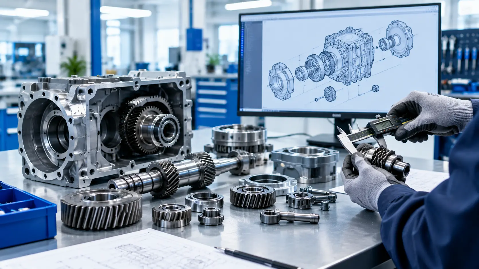
There are thousands of perfectly good parts in the world with no digital record behind them. Legacy machinery, discontinued components, worn-out tooling, the physical part exists but the original drawings are long gone.
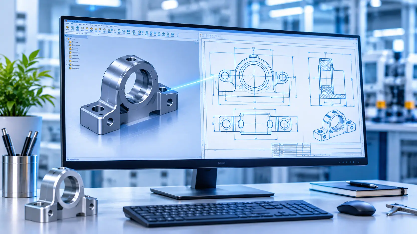
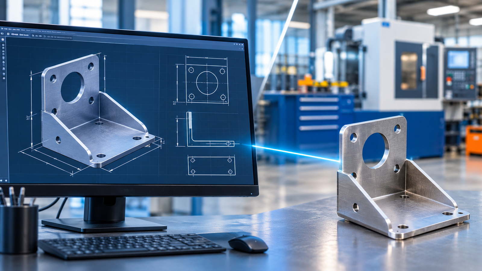
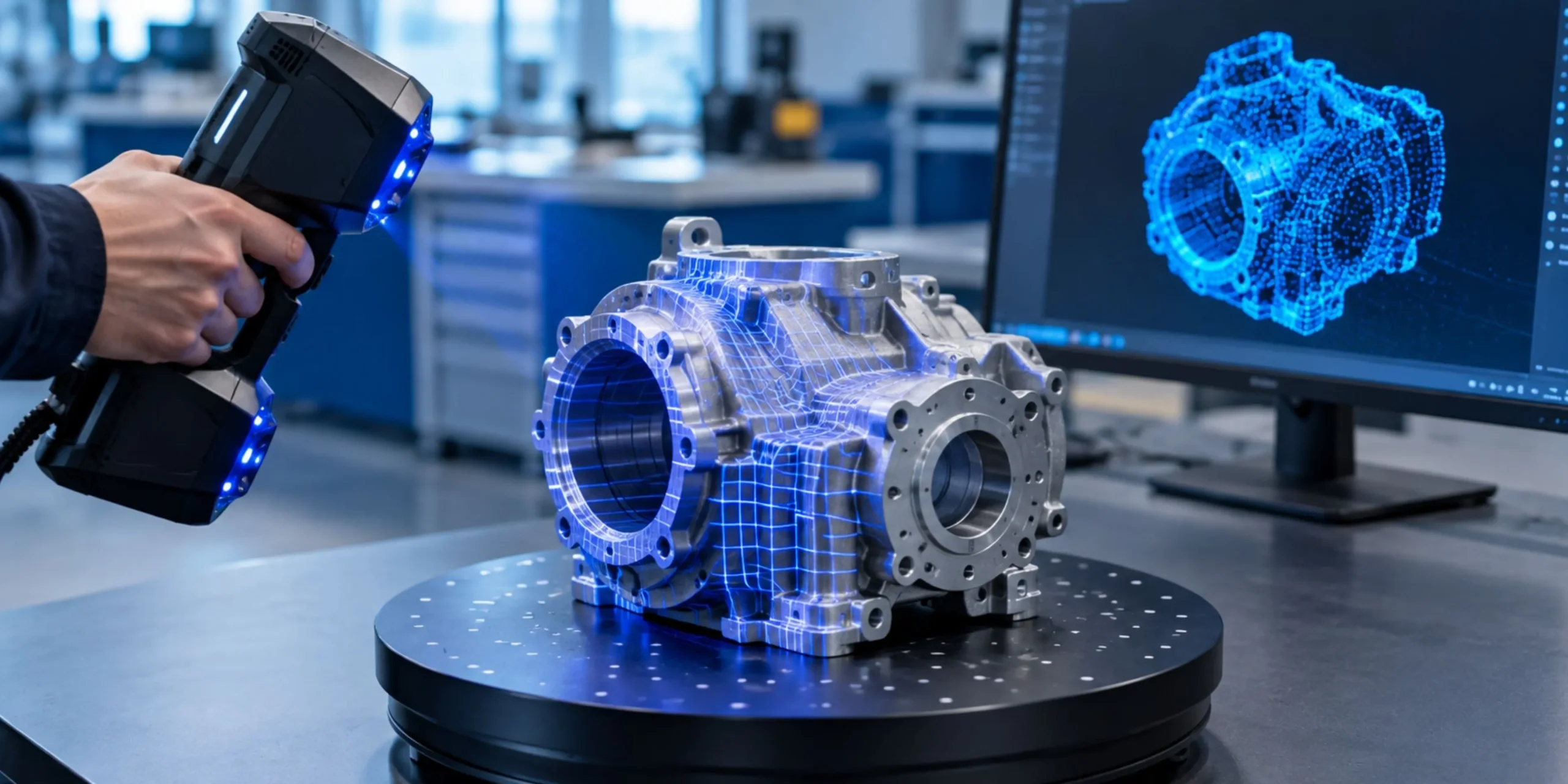
That is exactly where 3D scanning and scan-to-CAD conversion becomes critical. You capture the geometry of an existing part using a scanner, then rebuild a clean, parametric CAD file that a manufacturer can actually use.
It sounds straightforward. But skip one step in the process and your model will not match tolerances, will fail inspection, or will cause expensive rework on the shop floor. Here is what the process actually looks like, before, during, and after the scan.
Why Scan-to-CAD Conversion Matters in Real Manufacturing
When you are working with legacy parts, obsolete components, or designs that have no documentation, you cannot estimate dimensions. You need exact geometry captured from the real object.
A 3D scan captures that physical reality. But raw scan data, whether it is a point cloud or a mesh, is not something a CNC machine can use directly. Converting it into a parametric, editable CAD model is what makes the geometry manufacturable.
This conversion process is the core of what professional reverse engineering services are built to handle. You are not creating something new from scratch. You are recovering or improving something that already exists in physical form. That distinction matters because the goal is accuracy, not creativity.
Before You Scan: The Prep Work That Decides Everything
What you do before touching the scanner has more impact than most engineers expect. Poor preparation leads to patchy scan data, missing geometry, and models that take twice as long to clean up.
Choose the Right Scanning Method for the Job
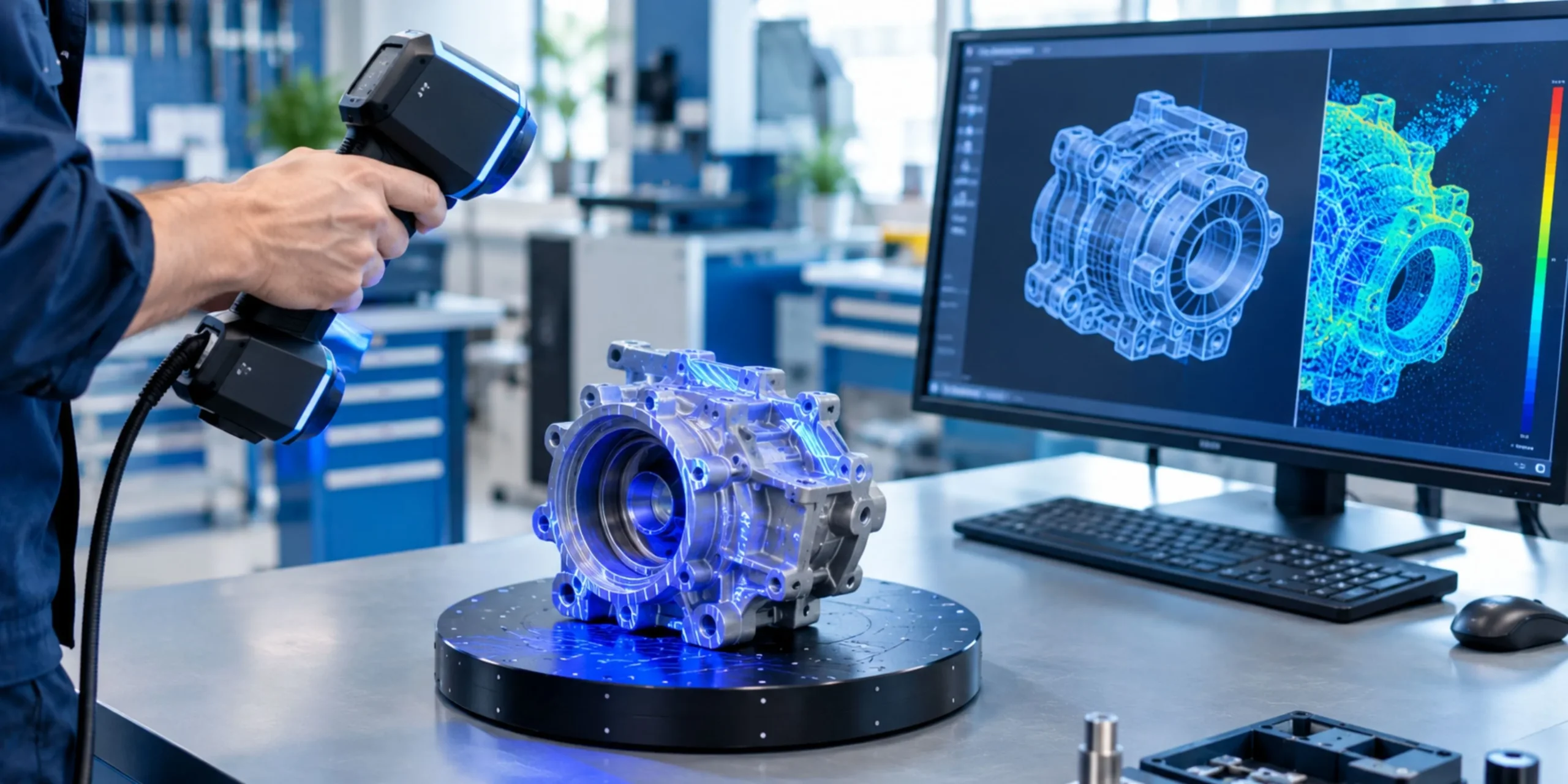
Not every scanner suits every part. Structured light scanners work well for smaller components where surface detail is critical. Laser trackers handle large assemblies, conveyor frames, and structural components more effectively.
For large outdoor environments, photogrammetry tools like Autodesk ReCap or RealityCapture capture geometry where a handheld scanner would be impractical. Know the object before you pick the method.
Surface material matters too. Shiny, reflective, or translucent surfaces cause significant scanner noise and errors. Apply a matte scanning spray before you begin. It takes a few minutes and saves hours of cleanup later.
Define the Accuracy Level You Actually Need
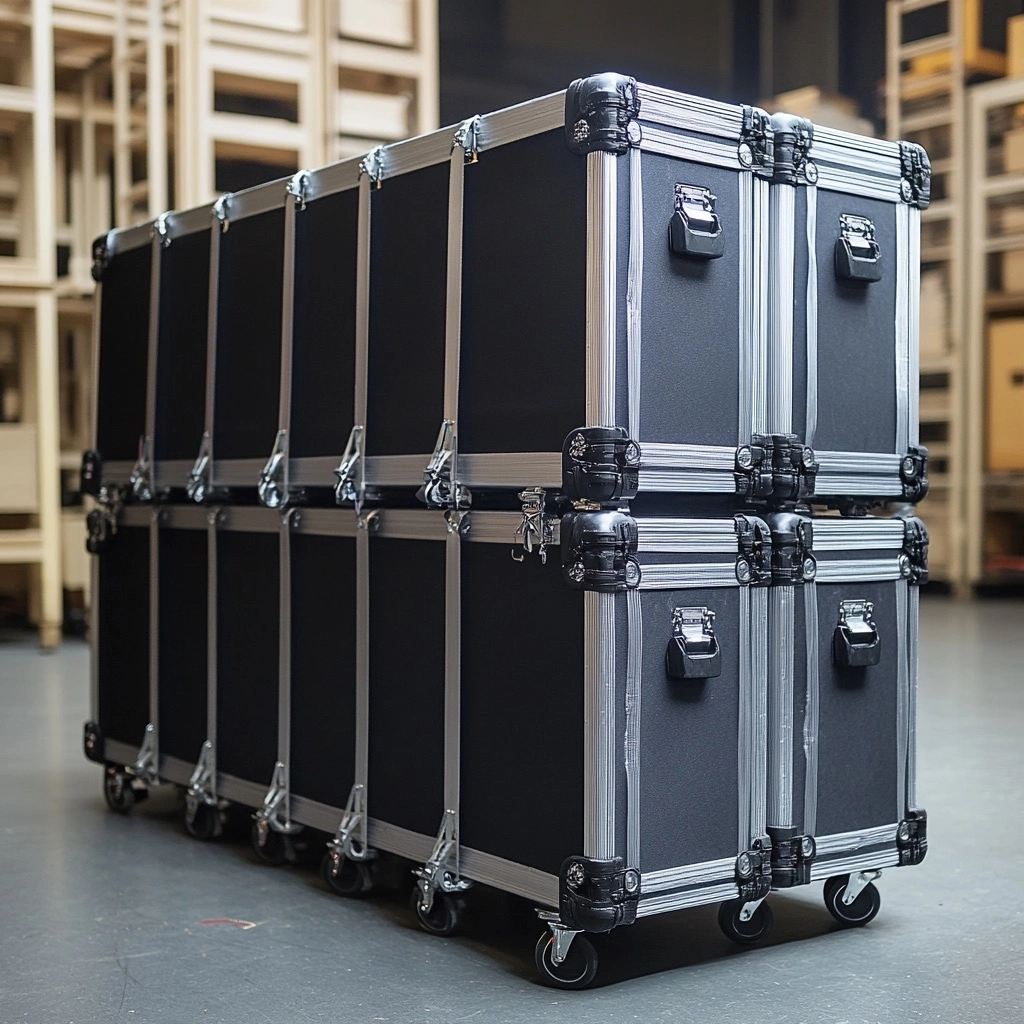
Not every part requires micron-level precision. A road case bracket has very different tolerances than a hydraulic pump housing or a bearing seat.
Before scanning, document the required tolerances and identify the critical features, mating surfaces, threaded holes, datum references. This way you know exactly where to focus during scan data cleanup and CAD reconstruction. It also makes final validation against manufacturing specs much faster.
If you are unsure what tolerance class applies, look at the part’s function. Load-bearing or tight-fit components need tighter accuracy than non-structural brackets.
During the Scan: Capture Complete, Usable Data
The scanning phase is about coverage and consistency. You want no data gaps, no overlapping distortions, and a uniform point density across the whole part.
Move around the object systematically. Keep each scan pass overlapping the previous one by at least 20-30% so the software can stitch them together accurately. Do not jump around the object randomly, work in a consistent path.
Pay extra attention to edges, small holes, internal channels, and undercuts. These features are most likely to have data gaps and they are also the most important for downstream CAD design services and manufacturing.
Keep the scanning environment stable. Vibration, part movement, and changing lighting all affect structured light scanners. If the shop floor is busy, scan after hours in a more controlled space.
From Point Cloud to Accurate CAD Model
This is where the real engineering work happens. Converting raw scan data into a clean, editable CAD model is not automatic, it takes skill, software knowledge, and manufacturing awareness.
The first step is processing the raw scan into a usable mesh. That means aligning multiple scan passes, filling gaps in the data, and reducing noise. Once the mesh is clean, you move into the actual CAD rebuild.
Using Geomagic Reverse Engineering Software
Geomagic reverse engineering tools, specifically Geomagic Design X, are the industry standard for scan-to-CAD conversion. The software lets you fit geometric primitives like planes, cylinders, and spheres to regions of the mesh and extract precise dimensional data from them.
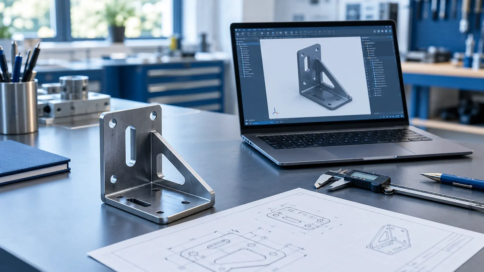
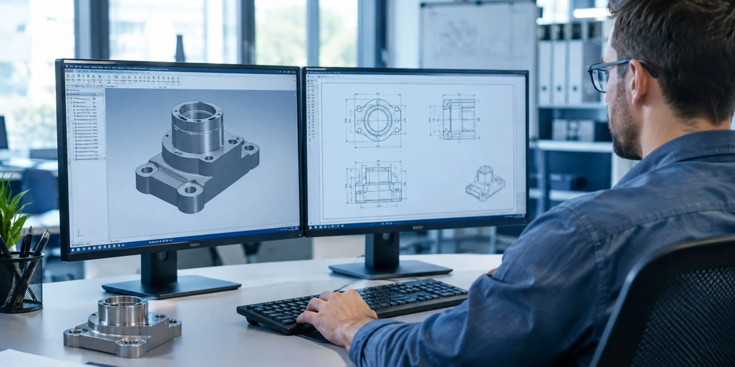
The CAD model is then rebuilt parametrically inside SolidWorks or Inventor. Parametric means the geometry is driven by actual dimensions and relationships, not just a frozen shape. That makes it fully editable and ready for manufacturing downstream.
For freeform or organic shapes, like ergonomic housings, complex brackets, or medical devices, you build Class-A surfaces from the mesh instead. This gives you smooth, high-quality geometry that holds its form through manufacturing. You can read more about the Geomagic Design X workflow to understand how the surface fitting and CAD export process works in detail.
Whatever the geometry type, the final output should be a fully closed solid model. No open faces, no overlapping surfaces, and no missing geometry.
Validating Your CAD Model Before It Goes to Manufacturing
You do not just hand over a CAD file and assume it is correct. Validation before manufacturing is not optional.
Run a deviation analysis by comparing the finished CAD model against the original scan data. This shows exactly where the CAD geometry drifts from the actual physical part. Most engineering teams accept deviations within 0.1mm to 0.2mm depending on the application.
Check critical features one by one, thread sizes, hole positions, wall thicknesses, mating surfaces. If the part is going to CNC machining, put it through a design for manufacturing review first. This catches features that are hard or expensive to machine, walls that are too thin, and tolerances that inflate cost without improving function.
If the part will see load, heat, or vibration in service, run a basic simulation on the CAD model before committing to manufacturing. Catching a failure mode in the CAD stage costs almost nothing compared to finding it after the part is machined.
Common Mistakes That Slow Down Manufacturing
A few errors appear repeatedly in scan-to-CAD projects. Knowing them upfront saves significant time.
- Skipping surface prep. Reflective or dark surfaces produce noisy scan data that takes much longer to clean up and still may not give you clean geometry in the end.
- Using the mesh as the final model. A mesh can look complete on screen but will fail when you try to machine from it. Always rebuild to a parametric CAD solid.
- Ignoring datum references. If the original part was designed around specific datum planes, understand and replicate them. It makes assembly and quality inspection far easier.
- Not checking against manufacturing tolerances. A geometrically complete model that ignores your machine shop’s capabilities will come back for revision.
For a deeper look at the tools and decisions involved, see our guide on reverse engineering tools for mechanical product development.
When to Use Professional Reverse Engineering Services
Not every team has the calibrated scanning hardware, Geomagic licenses, or process experience to handle complex scan-to-CAD projects in-house.
If you are dealing with high-tolerance parts, organic geometry, critical assemblies, or tight delivery windows, professional reverse engineering services reduce your risk significantly. Experienced teams scan daily, work in Geomagic and SolidWorks every week, and understand what a model needs to be actually manufacturable, not just geometrically complete.
If this is your first scan-to-CAD project, or the part is important enough to get right the first time, outsourcing makes sense. Read more about how 3D reverse engineering recreates parts without original CAD files to understand the full scope of what is possible.
Get It Right the First Time
Converting 3D scan data into a usable CAD model is a structured process. Every step matters, from surface prep and scan coverage to parametric rebuilding and deviation validation.
Cut corners in prep and you will pay for it in cleanup. Skip validation and your manufacturing run becomes a test run. Do it right and you get a model that machines cleanly, assembles correctly, and performs as designed.
If your team needs support at any stage of this workflow, Keyway’s reverse engineering services and CAD design services are built for exactly this kind of work. Get in touch and tell us what you are working on.
Further reading: Solving Product Design Challenges with 3D Reverse Engineering | Mechanical Reverse Engineering for Accurate Product Redesign | Complete Guide to CAD Design Services for Manufacturing