
Every engineer knows the frustration of a part coming back wrong from the shop. The tolerances were off. The finish wasn’t specified. A key dimension was missing. Most of the time, the problem started well before the machinist touched the material – it started with a poor drawing.
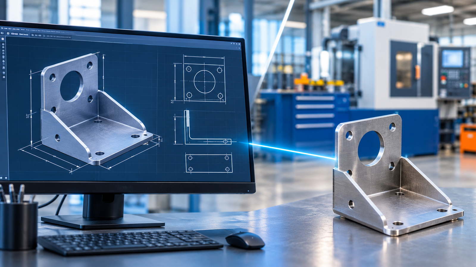
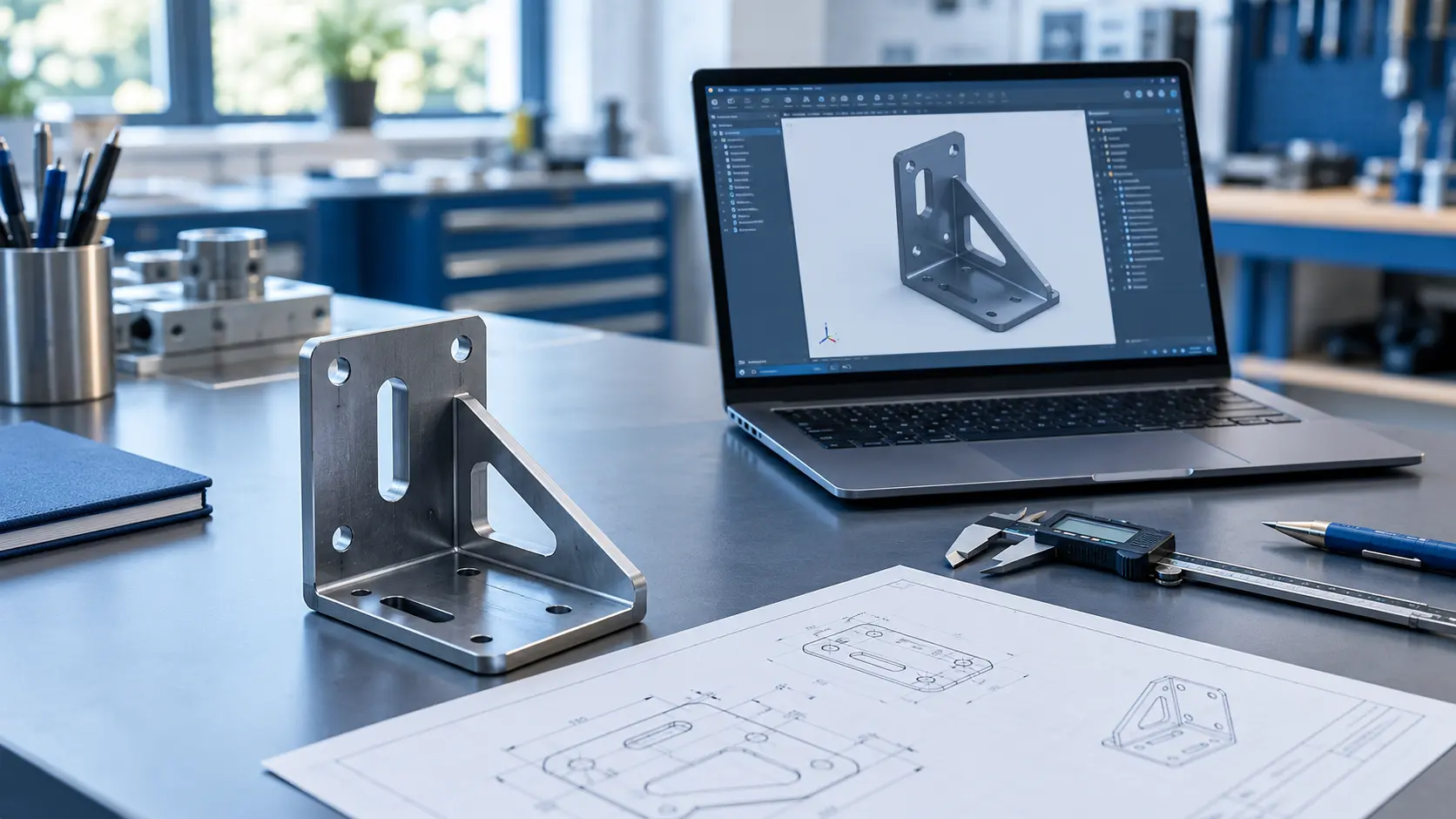
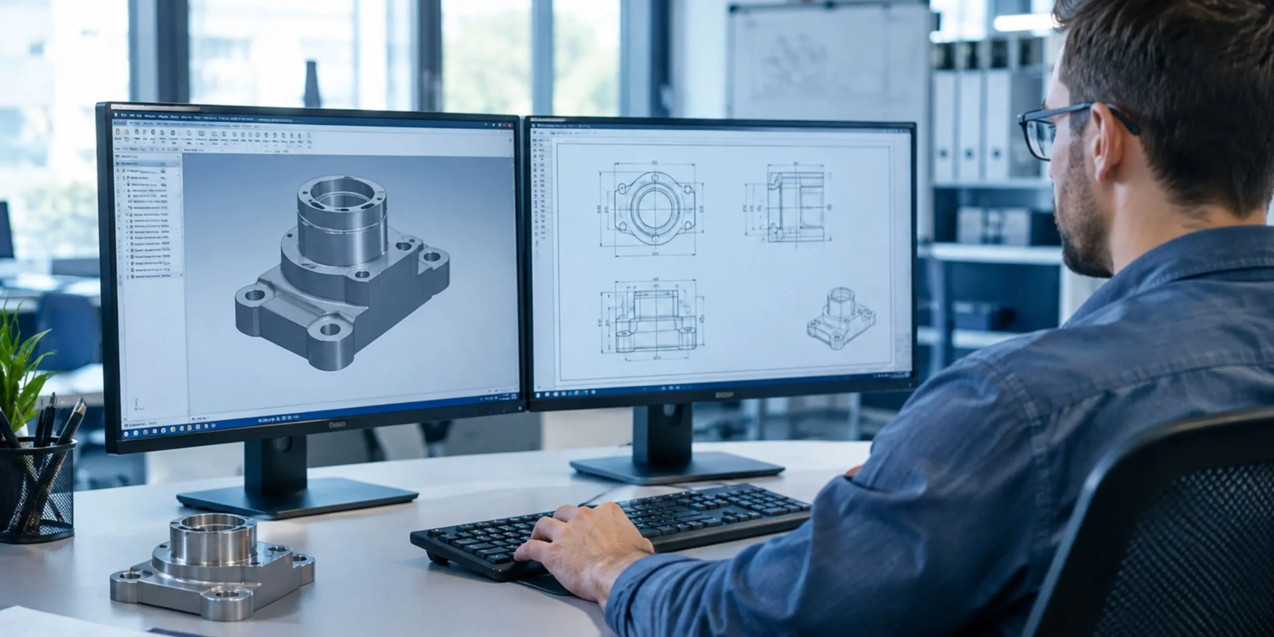
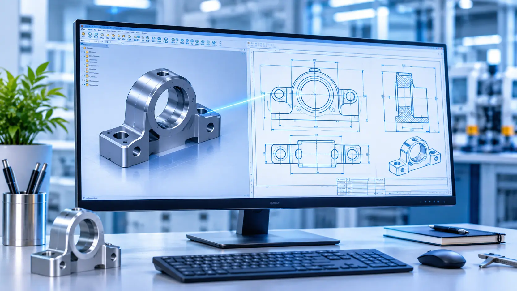
That’s where 2D drafting in SolidWorks changes the game. It gives you a direct path from a 3D model to a shop-ready, fully detailed engineering drawing – one that leaves no room for guesswork.
This guide covers what you need to do before, during, and after creating your SolidWorks drawings, so your team, your clients, and your manufacturers all stay on the same page.
Why 2D Drawings Still Matter in Engineering
It’s tempting to think 3D models have replaced traditional drawings. They haven’t.
A 3D model is a geometry file. It tells you what a part looks like, but it doesn’t tell a machinist what tolerances to hold, what surface finish to apply, or which features are critical. A 2D drawing does all of that.
For industries like aerospace, defense, and medical devices, a stamped 2D drawing is a legal document. It goes into audit files and quality records. It’s referenced years after a product ships.
Skilled CAD Drawing Services professionals know that a well-made 2D drawing is not an afterthought – it’s the foundation of every manufactured part.
Before You Start: Setting Up for Success
Good drawings come from good preparation. Skipping setup is the fastest way to create drawings that look unprofessional and cause downstream errors.
Choose the Right Drawing Standard
SolidWorks supports ANSI (American) and ISO (European) standards. Know which standard your client or manufacturer uses before you open a drawing file. Using the wrong projection angle or dimension style wastes everyone’s time.
Build a Drawing Template
A drawing template is a reusable file that includes your title block, sheet format, units, and default annotation styles. Set this up once, and every drawing you create will start from a consistent baseline.
Templates are especially important if you work with a team. Without them, you get five different title block styles from five different engineers.
Keep Your 3D Model Clean
2D drafting in SolidWorks is directly tied to your 3D model. If the model has suppressed features, broken references, or inconsistent naming, your drawing will reflect those problems. Resolve model errors before you even open a new drawing sheet.
This prep work is what separates fast, error-free SolidWorks Drafting from the kind that sends you back to the drawing board three times.
During Drafting: Building Accurate Engineering Drawings
Once your template and model are ready, the actual drafting process moves quickly – if you know what you’re doing.
Placing Views With Purpose
SolidWorks makes it easy to place views, which also makes it easy to place too many views. Each view on your sheet should answer a specific question. The front view, top view, and right-side view form your standard orthographic set. Add a section view to show internal features. Add a detail view to zoom in on complex geometry.
Don’t add views just to fill space. A cluttered drawing is harder to read than a simple one.
Dimensioning Smartly
SolidWorks lets you import dimensions from the model using the Model Items tool. This is fast, but it doesn’t always produce a clean drawing. Model dimensions can appear in unexpected places or overlap with views.
Use Smart Dimension to add or reposition dimensions manually where needed. Keep these rules in mind:
- Dimension to visible edges, not hidden lines
- Place dimensions outside the part boundary when possible
- Avoid dimension strings that cross each other
- Group related dimensions so the machinist reads them in a logical sequence
Adding Tolerances and GD&T
This is where many engineers cut corners – and where most shop errors originate.
Every critical dimension needs a tolerance. SolidWorks supports standard bilateral tolerances, limit tolerances, and full GD&T symbols. Use GD&T for form, orientation, location, and runout requirements. It communicates intent more precisely than a plain ± value.
If your team handles complex parts, consider working with a specialist in CAD Drawing Services who understands GD&T fully. A missed flatness callout on a sealing surface can shut down an entire production run.
Section Views, Detail Views, and Callouts
Section views slice through your part to reveal internal features – threads, bores, internal channels. Detail views zoom in on small features that would be illegible at the standard sheet scale.
Use callouts to reference standards, finishes, and inspection requirements. A clean callout saves a machinist from having to call you to ask what “finish per drawing” means.
Managing Assemblies: Drawings That Go Beyond Single Parts
Assembly drawings add another layer of complexity. They need:
- Balloons that identify each component
- Bills of Materials (BOM) listing part numbers, descriptions, and quantities
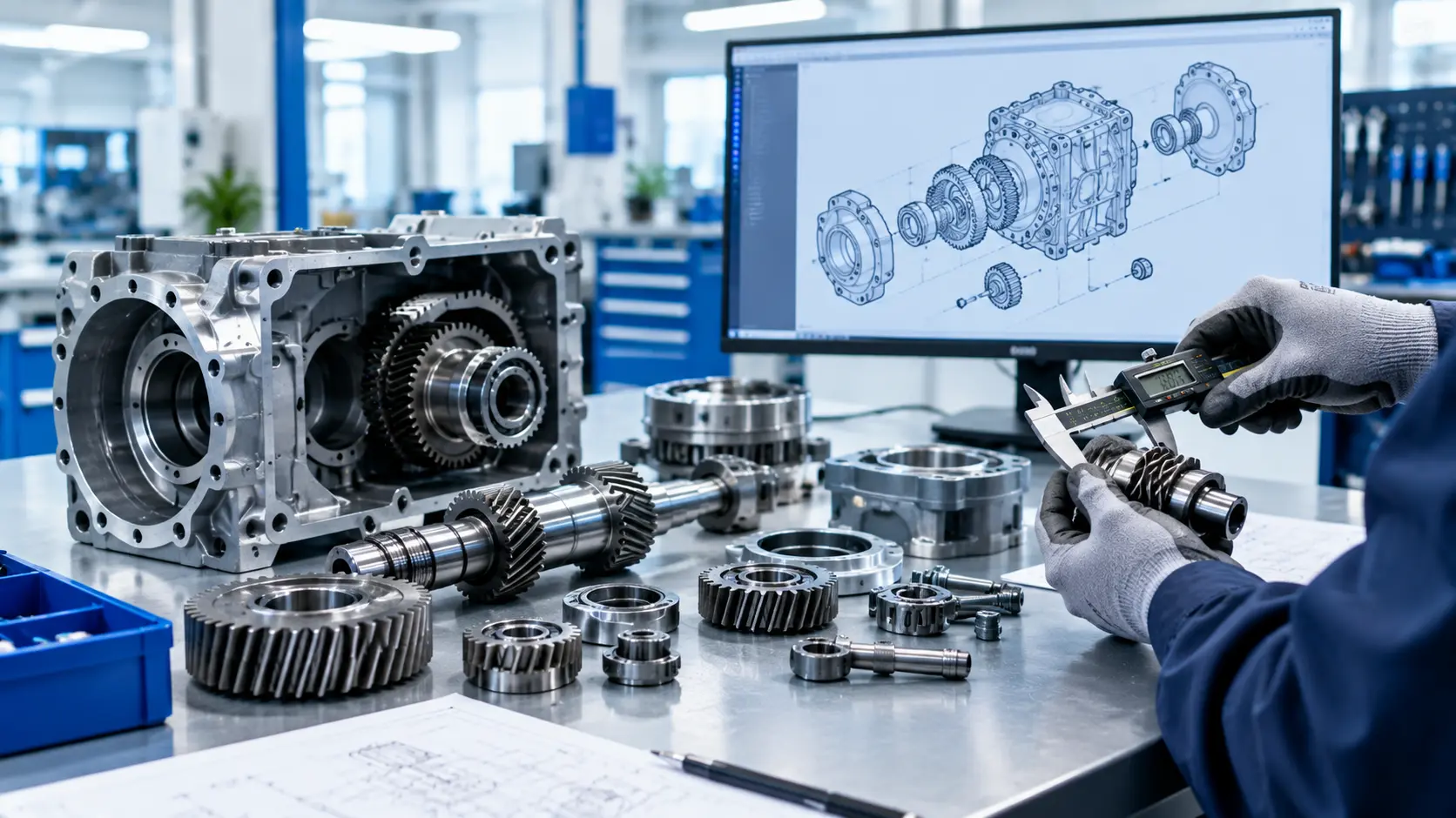
- Exploded views that show how the assembly goes together
SolidWorks generates the BOM automatically from the assembly model. But you still need to verify part numbers, check for missing components, and confirm that the BOM matches the actual assembly structure.
For complex assemblies – like those used in conveyor system design or industrial machinery – assembly drawings become critical manufacturing documents. A wrong balloon number means the wrong part gets installed.
After Drafting: Review, Release, and Revisions
A drawing isn’t done when you’re done dimensioning it. It’s done when it’s been reviewed, released, and confirmed as production-ready.
The Review Process
Walk through every sheet before releasing a drawing. Check:
- Are all features dimensioned?
- Do tolerances match the design intent?
- Is the title block complete – material, finish, revision level, drawing number?
- Do notes reference the correct standards?
- Is the BOM accurate for assemblies?
A second set of eyes is worth more than any checklist. Have a colleague review critical drawings before release. This is standard practice in any serious Mechanical Design Services workflow.
Revision Control
Drawings change. The key is tracking those changes with a revision block. Each revision gets a letter (A, B, C…), a description of what changed, and a date. Manufacturing always works from the latest revision.
Without revision control, an old drawing can make it to the shop floor. That’s how you end up making obsolete parts.
File Management and Output Formats
SolidWorks drawings are saved as .SLDDRW files. For sharing with manufacturers, export to PDF or DXF depending on what the shop requires. PDF is the most universal format – it’s readable anywhere, printable, and preserves all annotations.
If you work with manufacturers who use their own AutoCAD Drafting Services, provide DWG or DXF exports so they can open the files in their tools.
For part programs, your team may use the drawing as reference when setting up CAM Service operations. Clear, well-dimensioned drawings reduce setup time significantly.
Common Mistakes That Kill Drawing Quality
Even experienced SolidWorks users make these errors. Know them so you can avoid them.
Missing tolerances. An undimensioned feature leaves the machinist guessing. They’ll make a decision – it just might not be the right one.
Overcrowded sheets. Trying to fit everything onto one sheet can make the drawing unreadable. Use multiple sheets if needed.
Ignoring sheet scale. A tiny part drawn at 1:10 scale makes fine features impossible to dimension clearly. Set the scale before you start placing views.
Skipping the title block. A drawing without a title block is an informal sketch, not an engineering document. It won’t hold up in a contract dispute or a quality audit.
Not checking after model changes. When the 3D model updates, review the drawing. Some changes break existing dimensions or require new views. Don’t assume the drawing still matches the model.
When to Bring in Professionals
Not every company has the in-house capacity to handle complex drafting projects at scale. If you’re running short on drafting staff, managing a high volume of drawings, or handling unfamiliar standards, working with a CAD Drawing Services provider makes sense.
Professional drafters who specialize in SolidWorks Drafting bring speed, consistency, and deep knowledge of manufacturing tolerances. They’ve seen enough drawings to know what works and what doesn’t.
For companies that need drafting staff on a flexible basis, Drafting Staffing Agencies offer access to certified SolidWorks professionals without the overhead of full-time hiring.
Conclusion
2D drafting in SolidWorks is not a task you rush through. It’s the final step between your design intent and what actually gets built. Get it right, and manufacturing runs smoothly. Get it wrong, and you’re looking at costly rework, production delays, and frustrated clients.
Prepare your model and templates before you start. Use views, dimensions, and tolerances with precision during drafting. And after the drawing is done, review it carefully before it leaves your desk.
Ready to level up your drafting output – or need a team to handle it for you? Explore our SolidWorks Drafting services and see how we support engineering teams from first sketch to final release.
Frequently Asked Questions
What is 2D drafting in SolidWorks?
2D drafting in SolidWorks is the process of creating detailed engineering drawings from 3D part or assembly models. These drawings include dimensions, tolerances, notes, and views that communicate manufacturing requirements to machinists and fabricators.
How does SolidWorks drafting differ from AutoCAD drafting?
SolidWorks drafting is model-driven – drawings link to 3D models and update automatically when the model changes. AutoCAD Drafting Services are typically standalone 2D files. SolidWorks is better suited for mechanical parts and assemblies where 3D-to-2D accuracy matters.
What are the main views used in SolidWorks drawings?
The standard views are front, top, and right-side orthographic projections, plus section views and detail views. For assemblies, exploded views are also common. Our CAD Drawing Services team selects views based on what the manufacturer actually needs to understand the part.
How do I add tolerances to a SolidWorks drawing?
Tolerances are added through the dimension properties panel. You can set bilateral, limit, or symmetric tolerances, or use GD&T symbols for geometric controls. If your parts require tight tolerances, our Mechanical Design Services team can help ensure the tolerances match your design intent.
Can SolidWorks drawings be used directly for manufacturing?
Yes. SolidWorks drawings exported as PDF or DXF are used directly on the shop floor. They serve as the primary reference for machining, fabrication, and inspection. Many CAM Service setups also reference SolidWorks drawings for tool path programming.
What is a Bill of Materials in a SolidWorks assembly drawing?
A BOM is an automatically generated table listing all components in an assembly, including part numbers, descriptions, and quantities. It links to balloons on the drawing that identify each part. This is critical for assembly instructions and procurement.
How do I maintain revision control in SolidWorks drawings?
SolidWorks includes a revision table that tracks drawing changes. Each revision gets a letter, a description of the change, and a date. Proper revision control ensures manufacturers always work from the latest, approved version.
When should I hire a professional for SolidWorks drafting?
When your team lacks SolidWorks expertise, is overloaded with projects, or needs drawings for unfamiliar manufacturing processes, it’s time to bring in specialists. Our SolidWorks Drafting service and Drafting Staffing Agencies options can fill that gap quickly.
What is the difference between a part drawing and an assembly drawing?
A part drawing details a single component – dimensions, tolerances, material, and finish. An assembly drawing shows how multiple parts fit together, with balloons and a BOM. Both are core outputs of CAD Drawing Services.
Can SolidWorks handle GD&T in 2D drawings?
Yes. SolidWorks fully supports GD&T symbols including flatness, perpendicularity, true position, and runout. Applying GD&T correctly requires knowledge of the ASME Y14.5 standard. If you need GD&T-compliant drawings, our Mechanical Design Services team has that expertise.