
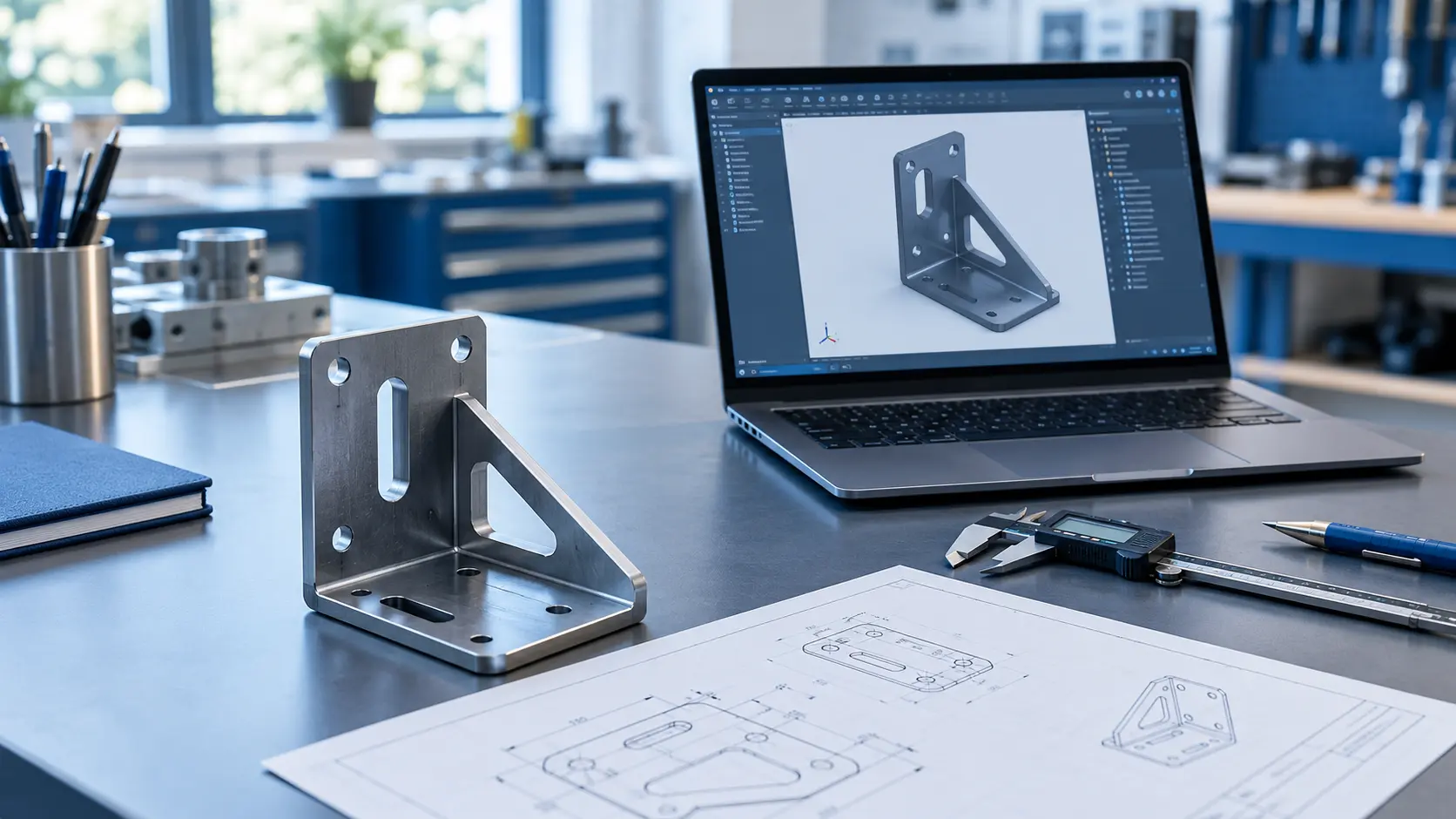
A flat sheet of metal looks simple. Then you try to bend, cut, and weld it into a real product, and the problems start. Holes distort, bends crack, and parts refuse to fit. Most of these issues begin on the drawing board, not on the shop floor. A professional sheet metal design service catches these problems early and saves you time, money, and frustration.
This guide explains how sheet metal design for manufacturing works. You will learn the key rules, common mistakes, and practical tips that help your parts move smoothly from CAD to finished product.
What Is Sheet Metal Design for Manufacturing?
Sheet metal design for manufacturing means designing parts so fabricators can produce them easily, accurately, and affordably. Engineers often call this approach Design for Manufacturing, or DFM.
DFM asks one simple question: can the shop build this part without trouble? If the answer is no, you change the design before production begins. That small step prevents expensive rework later.
Good DFM balances three goals. The part must work well, cost less to make, and stay consistent across large batches. When you hit all three, your product wins on quality and price.
Why DFM Matters in Sheet Metal Projects
Fabrication involves several steps. A shop cuts the blank, bends it, adds hardware, welds the seams, and finishes the surface. Each step adds cost and risk.
A poor design multiplies that risk. A hole too close to a bend can stretch and deform. A flange that is too short can slip out of the press brake tooling. Each fix costs money, and each delay pushes back your launch date.
Smart DFM delivers clear benefits:
- Lower unit costs through simpler tooling and faster cycle times
- Fewer prototypes and design revisions
- Better part quality and tighter consistency
- Shorter lead times from concept to production
- Less material waste
Teams that apply DFM from day one avoid most of these headaches.
Core Design Rules for Sheet Metal Parts
Every fabricator follows a set of basic rules. Learn these, and your designs will improve right away.
Choose the Right Bend Radius
The bend radius controls how well the metal folds without cracking. A radius that is too tight stresses the outer surface. A radius that is too large wastes space and changes the part’s shape.
As a general rule, set the inside bend radius equal to the material thickness. Harder materials like stainless steel or aluminum alloys may need a larger radius. Keep the same radius across all bends in a part. This lets the shop use one tool setup and finish the job faster.
Place Holes and Slots Carefully
Holes near a bend line distort when the metal stretches. Keep holes at least two times the material thickness away from any bend. Slots need even more room.
Hole size matters too. A punched hole should be at least as wide as the sheet is thick. Smaller holes can break the punch and slow production. If you need a tiny hole, ask your fabricator about laser cutting instead.
Add Bend Relief and Corner Relief
Bend relief is a small cut at the end of a bend line. It stops the metal from tearing where the flange meets flat material. Without it, you get ragged edges and weak corners.
Make the relief width at least half the material thickness. Round the corners where two bends meet. Sharp inside corners create stress points that can crack under load.
Respect Minimum Flange Length
A flange needs enough length for the press brake die to grip it. As a rule, make the flange at least four times the material thickness. Shorter flanges slip, bend unevenly, or need special tooling that raises the price.
Select the Right Material
Material choice affects strength, weight, cost, and how easily the metal bends. Pick it early, because it shapes every other design decision.
Here are the most common options:
- Mild steel: Cheap, strong, and easy to form. It needs a coating to resist rust.
- Stainless steel: Resists corrosion and looks clean. It costs more and springs back after bending.
- Aluminum: Light and corrosion resistant. It bends easily but cracks if you bend it too sharply.
- Copper and brass: Great for electrical parts and decorative work, though they cost more.
Think about the product’s environment. A food processing machine needs stainless steel. A drone housing needs lightweight aluminum. Match the metal to the job, not just the budget.
Set Smart Tolerances
Tolerances tell the fabricator how much a dimension can vary. Many engineers make the mistake of setting them too tight everywhere. Tight tolerances demand slower processes and more inspection, and both raise costs.
Apply tight tolerances only where fit or function requires them. Use standard tolerances for everything else. Laser cutting usually holds about ±0.1 mm, while bending typically varies by ±0.25 mm or more. Design around those realities.
Strong tolerance planning is part of the bigger picture of product development. Experienced mechanical design services help you decide where precision matters and where you can relax. That balance keeps your parts accurate and affordable.
Design Features That Simplify Assembly
Good sheet metal design makes assembly easier, not just fabrication. Think about how workers will put the product together.
Use self-locating features like tabs and slots. They guide parts into position and cut the need for fixtures. Add standard hardware, such as PEM nuts and studs, instead of custom fasteners. Standard parts cost less and arrive faster.
Keep the number of parts low. Can you fold one piece into a shape that replaces three welded pieces? Fewer parts mean fewer joints, less labor, and a stronger final product.
Common Sheet Metal Design Mistakes
Even experienced engineers slip up. Watch out for these frequent errors.
Ignoring Grain Direction
Metal sheets have a grain from the rolling process. Bending along the grain raises the risk of cracks. Bend across the grain whenever you can, especially with hard materials.
Forgetting Springback
Metal springs back slightly after you bend it. Stainless steel springs back more than mild steel. Your fabricator usually compensates, but you should flag critical angles in your drawing.
Overcomplicating the Geometry
Complex shapes need special tools and extra setups. Ask yourself if each feature is truly necessary. A simpler part often works just as well and costs far less.
Skipping the Flat Pattern Check
Every sheet metal part starts as a flat pattern. Check that your flat layout has no overlaps and that the bends unfold correctly. Most CAD tools offer a flat pattern view. Use it before you send files out.
Use Technology to Improve Your Designs
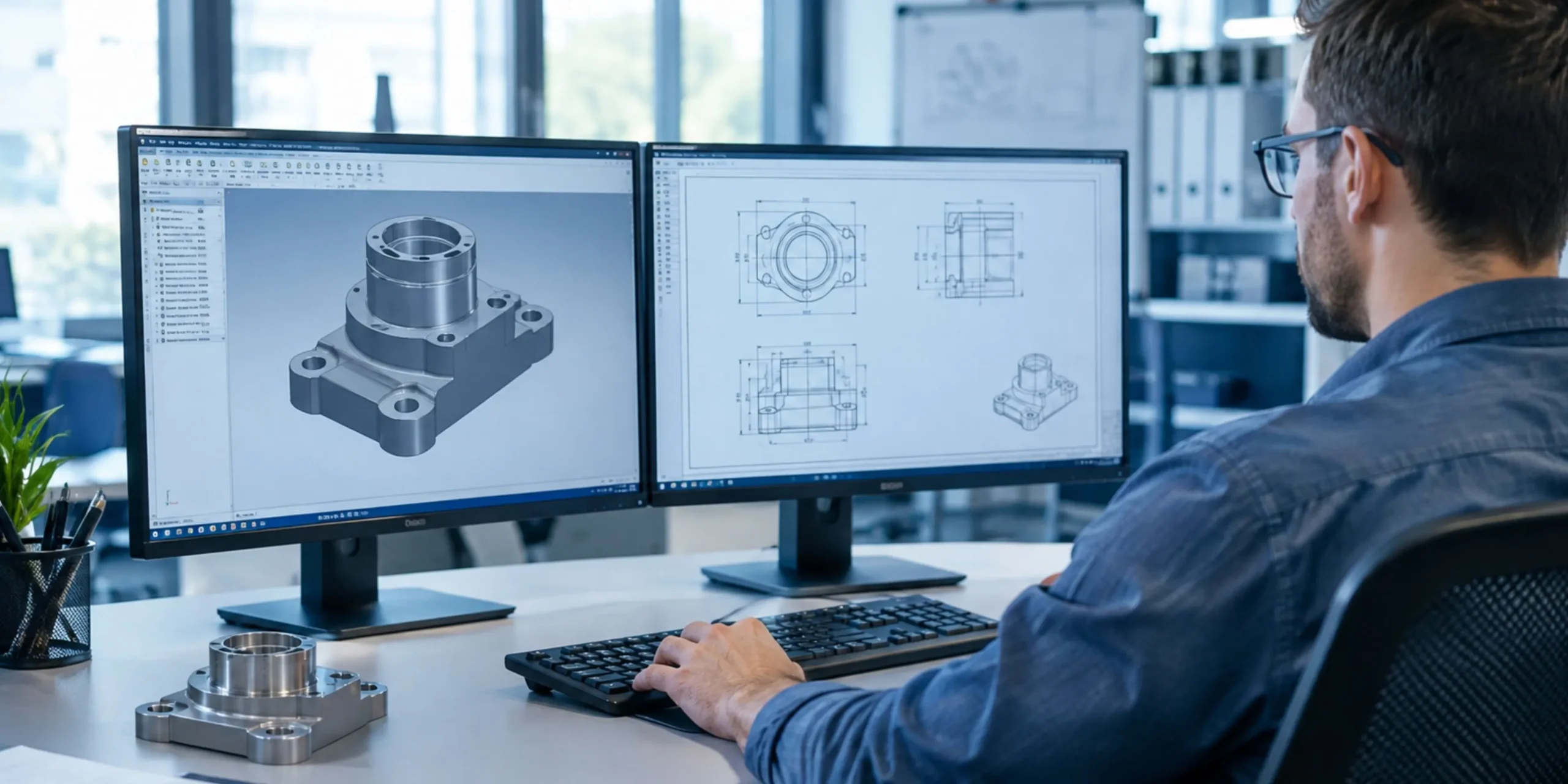
Modern CAD software makes DFM much easier. Programs like SolidWorks, Autodesk Inventor, and Fusion 360 include sheet metal modules. They calculate bend allowances, unfold parts, and flag errors automatically.
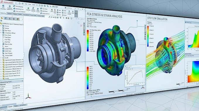
Simulation tools go further. They predict how the metal will deform and show you where cracks or wrinkles might appear. You can fix these issues on screen before you cut a single sheet.
Early prototypes still matter. A quick laser cut and bent sample reveals real-world problems that software can miss. Test fit, check the finish, and then refine the design.
When to Bring in a Design Partner
Some projects need extra expertise. You might lack in-house engineers. Maybe the product is complex, or the deadline is tight. In these cases, a design partner pays for itself.
A skilled partner reviews your concept, applies DFM rules, and prepares production-ready drawings. They also talk to fabricators in the language shops understand. That communication alone prevents many costly mistakes.
Many companies also need support beyond one part. They may want to rebuild an old component or move a new idea toward launch. If that sounds familiar, read this guide on mechanical design services, reverse engineering, and product development. It shows how a single engineering team can guide a product from first sketch to finished goods.
Quick DFM Checklist for Sheet Metal Parts
Run through this list before you release any design:
- Is the bend radius consistent and suited to the material?
- Do holes sit at least two times the thickness from every bend?
- Does every bend have proper relief?
- Are the flanges long enough for standard tooling?
- Did you apply tight tolerances only where needed?
- Does the flat pattern unfold without errors?
- Have you used standard hardware wherever possible?
- Did you consider grain direction and springback?
If you can answer yes to each one, your design is ready for the shop.
Final Thoughts
Great sheet metal parts start with great design choices. When you follow DFM principles, you cut costs, speed up production, and build better products. Focus on simple geometry, smart tolerances, and the right material. Check your flat patterns, test early, and talk to your fabricator often.
You do not have to handle it alone. The team at Keyway can support you from concept to production. Explore their sheet metal design service to turn your ideas into parts that manufacture smoothly. You can also follow their engineering insights and project updates on LinkedIn.
Design well, and manufacturing becomes the easy part.