
Every product failure that reaches a customer costs far more than one caught on a screen. That’s why more manufacturers now rely on professional Finite Element Analysis Services to simulate real-world stress, vibration, thermal load, and fatigue before a single physical prototype is built. Instead of discovering a weak weld, an overstressed bracket, or a fatigue crack after tooling is cut, engineering teams can identify and correct these issues digitally saving weeks of rework and thousands of dollars in scrapped parts.
What Is Finite Element Analysis (And Why It Matters)
Finite Element Analysis (FEA) is a computational method that breaks a complex part or assembly into thousands of smaller elements, then calculates how each element behaves under load, heat, vibration, or pressure. According to Wikipedia, the finite element method is a numerical technique used to find approximate solutions to boundary value problems for partial differential equations, widely applied in structural, thermal, and fluid analysis across engineering disciplines.
In practical terms, FEA lets engineers answer questions like:
- Will this bracket crack under repeated vibration?
- Where will stress concentrate on this weld joint?
- Can this enclosure survive a drop test?
- Will this assembly deform under thermal expansion?
Answering these questions before manufacturing is what separates a reliable product launch from an expensive recall.
How Design Failures Happen Without Simulation
Most costly design failures don’t come from bad engineering they come from untested assumptions. Common failure points include:
- Stress concentrations at sharp corners, holes, or fillets that aren’t visible until the part physically cracks.
- Fatigue failure from cyclic loading that only shows up after thousands of load cycles in the field.
- Thermal expansion mismatches between materials that cause warping or seal failure.
- Assembly-level interactions where individual parts pass inspection but fail once combined under real operating loads.
Physical prototyping alone often misses these issues because a prototype only reveals that something failed not why, or where the margin actually was.
Where FEA Analysis Solidworks Assembly Simulation Fits In
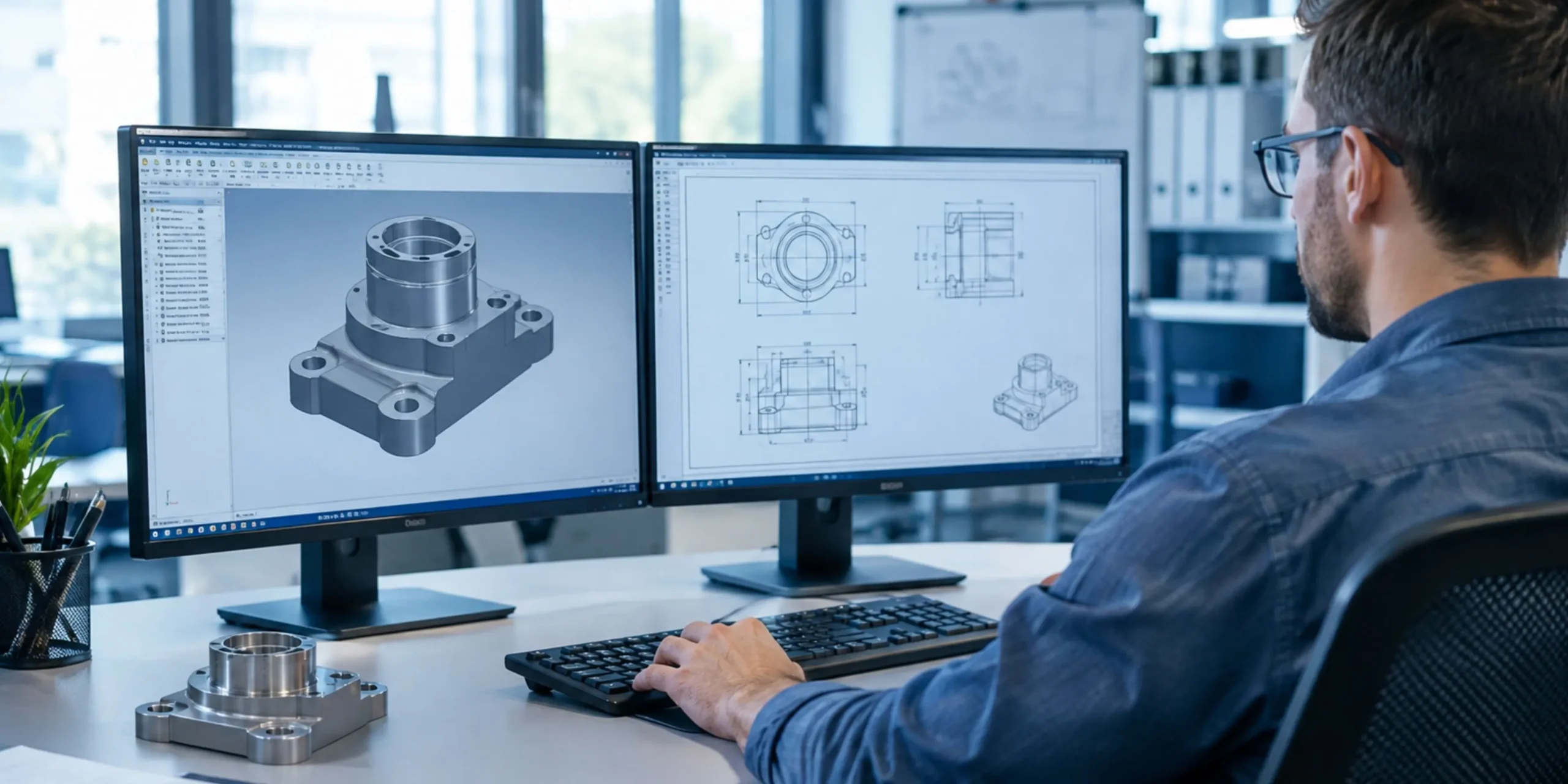
For teams already designing in SolidWorks, running FEA Analysis Solidworks Assembly simulations directly on the CAD model is one of the most efficient ways to validate a design before it leaves the digital environment. Because the simulation works from the native assembly file, engineers can:
- Test multiple load cases on the full assembly, not just isolated parts
- Identify how components interact bolted joints, press fits, contact surfaces
- Iterate on geometry changes and immediately re-run analysis without rebuilding a prototype
- Catch interference or stress issues introduced by tolerances between mating parts
This assembly-level view matters because failures rarely happen in a single component in isolation they happen at interfaces, joints, and load paths between parts.
The Business Case: Why FEA Pays for Itself
Without FEA | With FEA Services |
Multiple physical prototype rounds | Fewer prototypes, validated digitally first |
Failures discovered late, near production | Failures caught early, in the design phase |
Field failures and warranty claims | Reduced risk of in-service failure |
Overdesigned parts (excess material “just in case”) | Optimized geometry lighter, cheaper, still safe |
The cost of a single late-stage tooling change often exceeds the entire cost of a simulation study. This is the core economic argument for building FEA into the design workflow rather than treating it as an optional final check.
Common Applications of FEA in Product Design
- Structural analysis – verifying load-bearing components won’t yield or buckle
- Fatigue analysis – predicting part life under repeated stress cycles
- Thermal analysis – modeling heat distribution in enclosures, electronics, and engines
- Vibration and modal analysis – identifying resonance frequencies that could cause failure
- Drop and impact simulation – testing durability for consumer and industrial products
How the FEA Process Works, Step by Step
A professional simulation study isn’t a single button press it’s a structured process, and understanding it helps engineering teams know what to expect when they bring in outside FEA support.
- Model preparation – The CAD geometry is cleaned up and simplified where needed. Small features that don’t affect structural behavior (cosmetic fillets, logos, non-load-bearing holes) are often removed to keep the mesh manageable without sacrificing accuracy.
- Meshing – The part or assembly is divided into thousands (sometimes millions) of small elements. Mesh density is increased in high-stress areas like fillets, joints, and contact surfaces, and kept coarser elsewhere to balance accuracy with computation time.
- Defining materials and boundary conditions – Real material properties (yield strength, elastic modulus, thermal conductivity, fatigue curves) are assigned, along with how the part is constrained and loaded bolted supports, applied forces, pressure, temperature, or vibration input.
- Running the solver – The software calculates stress, strain, displacement, or temperature distribution across every element based on the defined loads and constraints.
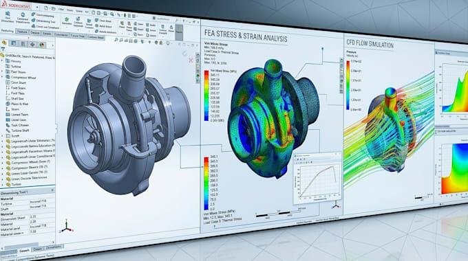
- Post-processing and interpretation – Results are reviewed as color-coded stress or displacement plots, and an experienced analyst checks whether high-stress regions make physical sense or indicate a modeling error that needs correction.
- Design iteration – If the part fails to meet its safety factor, geometry, material, or wall thickness is adjusted and the simulation is re-run often multiple times until the design meets its performance target.
This iterative loop is where most of the cost savings come from: each iteration in software takes hours, while each iteration with physical prototypes can take weeks and consume material, tooling, and lab time.
Real-World Scenario: Catching a Failure Before It Happens
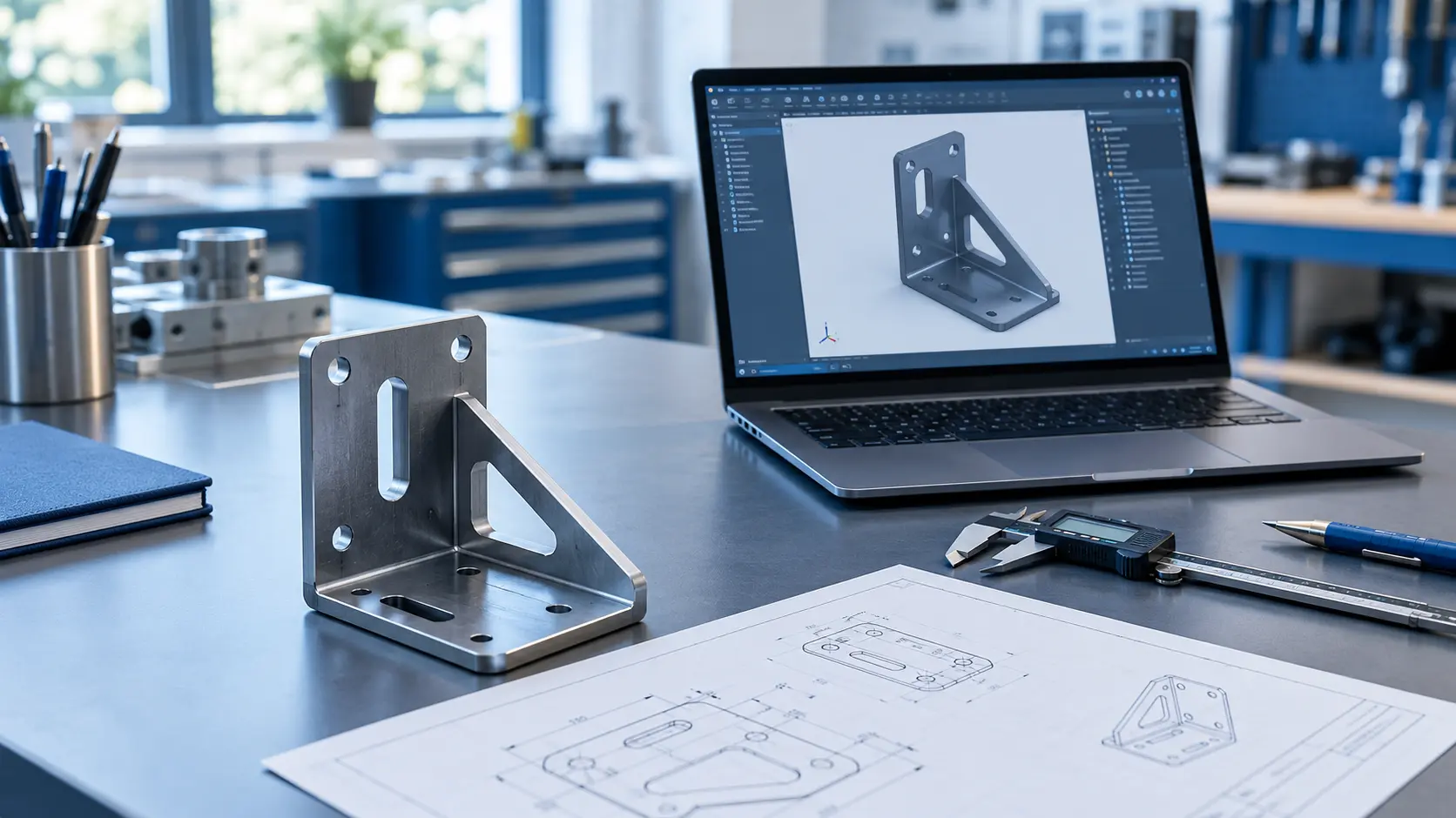
Consider a common example a sheet metal bracket designed to hold an electronic enclosure on a vehicle subject to constant road vibration. On paper, the bracket looks adequately sized. A static load calculation shows it can support the enclosure’s weight with margin to spare.
Run through FEA, however, a different picture emerges. The simulation reveals a stress concentration at a mounting hole that experiences amplified load during resonance at a specific vibration frequency the vehicle regularly encounters. Under static loading alone, this issue would never surface. Under real-world cyclic loading, it would eventually lead to a fatigue crack likely discovered only after units are already in the field.
By catching this in simulation, the engineering team can add a small fillet radius, adjust hole placement, or increase material thickness in just that region a change that costs almost nothing in software but would have triggered a field recall if it had reached production.
Choosing the Right FEA Services Partner
Not all simulation work delivers the same value. When evaluating a provider for Finite Element Analysis services, engineering teams should look for:
- Experience with your specific application – aerospace fatigue analysis requires different expertise than consumer electronics thermal modeling.
- Ability to work directly with your CAD platform – including SolidWorks assemblies, so results map directly back to the design without translation errors.
- Clear reporting, not just colorful stress plots a good analysis explains why a result matters and what design change addresses it.
- Validation experience – providers who understand how simulation results correlate with physical test data tend to produce more trustworthy, actionable results.
- Turnaround time that fits your design cycle, since simulation only saves money if it happens early enough to influence decisions.
Best Practices for Getting Accurate, Useful Results
Simulation is only as reliable as the assumptions behind it. A few practices consistently separate useful FEA studies from misleading ones:
- Use realistic material data rather than generic default values, especially for plastics, composites, and welded joints where properties vary significantly by manufacturing process.
- Apply loads and constraints that reflect actual in-service conditions, not just idealized worst-case static loads.
- Refine the mesh in critical regions rather than uniformly across the whole model, which keeps results accurate without excessive solve time.
- Cross-check simulation results against hand calculations or known benchmarks for a sanity check before trusting the output.
- Treat FEA as part of an iterative design process, not a one-time pass/fail gate at the end of development.
Final Thoughts
Design failures are rarely a surprise in hindsight; they’re usually the result of a load path, joint, or material limit that was never tested before production. Building simulation into the design cycle, rather than treating it as a final formality, is what allows engineering teams to catch these issues while they’re still cheap to fix. LinkedIn can also help engineering teams stay connected with industry insights, technical discussions, and emerging simulation practices. That’s the value KEYWAY brings to product teams: turning simulation data into design decisions before a single part is cut, so what reaches manufacturing has already proven it can hold up in the real world.