Blogs

How Finite Element Analysis Services Prevent Costly Design Failures

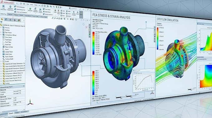
Every product failure that reaches a customer costs far more than one caught on a screen. That’s why more manufacturers now rely on professional Finite Element Analysis Services to simulate real-world stress, vibration, thermal load, and fatigue before a single physical prototype is built. Instead of discovering a weak weld, an overstressed bracket, or a fatigue crack after tooling is cut, engineering teams can identify and correct these issues digitally saving weeks of rework and thousands of dollars in scrapped parts.

What Is Finite Element Analysis (And Why It Matters)

Finite Element Analysis (FEA) is a computational method that breaks a complex part or assembly into thousands of smaller elements, then calculates how each element behaves under load, heat, vibration, or pressure. According to Wikipedia, the finite element method is a numerical technique used to find approximate solutions to boundary value problems for partial differential equations, widely applied in structural, thermal, and fluid analysis across engineering disciplines.

In practical terms, FEA lets engineers answer questions like:

  • Will this bracket crack under repeated vibration?
  • Where will stress concentrate on this weld joint?
  • Can this enclosure survive a drop test?
  • Will this assembly deform under thermal expansion?

Answering these questions before manufacturing is what separates a reliable product launch from an expensive recall.

How Design Failures Happen Without Simulation

Most costly design failures don’t come from bad engineering they come from untested assumptions. Common failure points include:

  1. Stress concentrations at sharp corners, holes, or fillets that aren’t visible until the part physically cracks.
  1. Fatigue failure from cyclic loading that only shows up after thousands of load cycles in the field.
  2. Thermal expansion mismatches between materials that cause warping or seal failure.
  3. Assembly-level interactions where individual parts pass inspection but fail once combined under real operating loads.

Physical prototyping alone often misses these issues because a prototype only reveals that something failed not why, or where the margin actually was.

Where FEA Analysis Solidworks Assembly Simulation Fits In

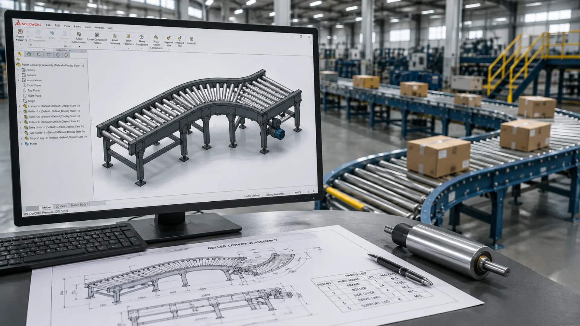
For teams already designing in SolidWorks, running FEA Analysis Solidworks Assembly simulations directly on the CAD model is one of the most efficient ways to validate a design before it leaves the digital environment. Because the simulation works from the native assembly file, engineers can:

  • Test multiple load cases on the full assembly, not just isolated parts
  • Identify how components interact bolted joints, press fits, contact surfaces
  • Iterate on geometry changes and immediately re-run analysis without rebuilding a prototype
  • Catch interference or stress issues introduced by tolerances between mating parts

This assembly-level view matters because failures rarely happen in a single component in isolation they happen at interfaces, joints, and load paths between parts.

The Business Case: Why FEA Pays for Itself

Without FEA

With FEA Services

Multiple physical prototype rounds

Fewer prototypes, validated digitally first

Failures discovered late, near production

Failures caught early, in the design phase

Field failures and warranty claims

Reduced risk of in-service failure

Overdesigned parts (excess material “just in case”)

Optimized geometry lighter, cheaper, still safe

The cost of a single late-stage tooling change often exceeds the entire cost of a simulation study. This is the core economic argument for building FEA into the design workflow rather than treating it as an optional final check.

Common Applications of FEA in Product Design

  • Structural analysis – verifying load-bearing components won’t yield or buckle
  • Fatigue analysis – predicting part life under repeated stress cycles
  • Thermal analysis – modeling heat distribution in enclosures, electronics, and engines
  • Vibration and modal analysis – identifying resonance frequencies that could cause failure
  • Drop and impact simulation – testing durability for consumer and industrial products

How the FEA Process Works, Step by Step

A professional simulation study isn’t a single button press it’s a structured process, and understanding it helps engineering teams know what to expect when they bring in outside FEA support.

  1. Model preparation – The CAD geometry is cleaned up and simplified where needed. Small features that don’t affect structural behavior (cosmetic fillets, logos, non-load-bearing holes) are often removed to keep the mesh manageable without sacrificing accuracy.
  1. Meshing – The part or assembly is divided into thousands (sometimes millions) of small elements. Mesh density is increased in high-stress areas like fillets, joints, and contact surfaces, and kept coarser elsewhere to balance accuracy with computation time.
  2. Defining materials and boundary conditions – Real material properties (yield strength, elastic modulus, thermal conductivity, fatigue curves) are assigned, along with how the part is constrained and loaded bolted supports, applied forces, pressure, temperature, or vibration input.
  3. Running the solver – The software calculates stress, strain, displacement, or temperature distribution across every element based on the defined loads and constraints.
  4. Post-processing and interpretation – Results are reviewed as color-coded stress or displacement plots, and an experienced analyst checks whether high-stress regions make physical sense or indicate a modeling error that needs correction.
  5. Design iteration – If the part fails to meet its safety factor, geometry, material, or wall thickness is adjusted and the simulation is re-run often multiple times until the design meets its performance target.

This iterative loop is where most of the cost savings come from: each iteration in software takes hours, while each iteration with physical prototypes can take weeks and consume material, tooling, and lab time.

Real-World Scenario: Catching a Failure Before It Happens

Consider a common example a sheet metal bracket designed to hold an electronic enclosure on a vehicle subject to constant road vibration. On paper, the bracket looks adequately sized. A static load calculation shows it can support the enclosure’s weight with margin to spare.

Run through FEA, however, a different picture emerges. The simulation reveals a stress concentration at a mounting hole that experiences amplified load during resonance at a specific vibration frequency the vehicle regularly encounters. Under static loading alone, this issue would never surface. Under real-world cyclic loading, it would eventually lead to a fatigue crack likely discovered only after units are already in the field.

By catching this in simulation, the engineering team can add a small fillet radius, adjust hole placement, or increase material thickness in just that region a change that costs almost nothing in software but would have triggered a field recall if it had reached production.

Choosing the Right FEA Services Partner

Not all simulation work delivers the same value. When evaluating a provider for Finite Element Analysis services, engineering teams should look for:

  • Experience with your specific application – aerospace fatigue analysis requires different expertise than consumer electronics thermal modeling.
  • Ability to work directly with your CAD platform – including SolidWorks assemblies, so results map directly back to the design without translation errors.
  • Clear reporting, not just colorful stress plots a good analysis explains why a result matters and what design change addresses it.
  • Validation experience – providers who understand how simulation results correlate with physical test data tend to produce more trustworthy, actionable results.
  • Turnaround time that fits your design cycle, since simulation only saves money if it happens early enough to influence decisions.

Best Practices for Getting Accurate, Useful Results

Simulation is only as reliable as the assumptions behind it. A few practices consistently separate useful FEA studies from misleading ones:

  • Use realistic material data rather than generic default values, especially for plastics, composites, and welded joints where properties vary significantly by manufacturing process.
  • Apply loads and constraints that reflect actual in-service conditions, not just idealized worst-case static loads.
  • Refine the mesh in critical regions rather than uniformly across the whole model, which keeps results accurate without excessive solve time.
  • Cross-check simulation results against hand calculations or known benchmarks for a sanity check before trusting the output.
  • Treat FEA as part of an iterative design process, not a one-time pass/fail gate at the end of development.

Final Thoughts

Design failures are rarely a surprise in hindsight; they’re usually the result of a load path, joint, or material limit that was never tested before production. Building simulation into the design cycle, rather than treating it as a final formality, is what allows engineering teams to catch these issues while they’re still cheap to fix. LinkedIn can also help engineering teams stay connected with industry insights, technical discussions, and emerging simulation practices. That’s the value KEYWAY brings to product teams: turning simulation data into design decisions before a single part is cut, so what reaches manufacturing has already proven it can hold up in the real world.
Complete Guide to CAD Design Services to Improve Modern Manufacturing Efficiency

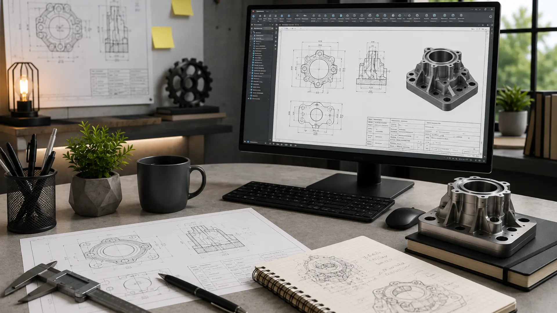
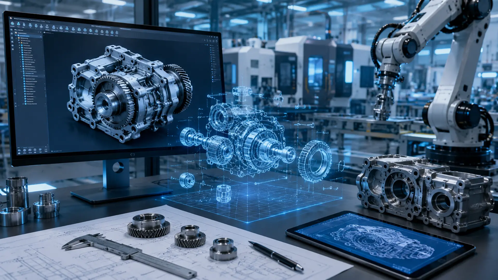
Efficient product development, accurate and quick manufacturing relies on modern manufacturing. From the creation of a new product to the enhancement of an existing one, businesses need to have the right digital designs to ensure successful manufacturing. Clear engineering drawings and detailed 3D models help to minimize production errors, enhance communication, and accelerate the overall development process. This is why CAD Design Services are an important role in today’s engineering and manufacturing.

Companies also use 3D CAD Modeling Services today to make detailed digital models before production. These models enable engineers to experiment with designs, refine them, and discover problems early in the design process. Consequently, manufacturers can save time, reduce costs, and confidently manufacture products of high quality.

What Are CAD Design Services?

These engineering services refers to the process of creating precise computer-aided design (CAD) drawings and 3D models. They provide services to engineers, designers and manufacturers to create products ready for production and minimize manual drafting and design mistakes.

CAD technology enables a company to design, modify and assess the product designs prior to manufacturing.

These services include:

  • Product design
  • Mechanical components
  • Assembly drawings
  • Manufacturing documentation
  • Engineering drawings
  • Prototype development
  • Design modifications
  • Production planning

Why CAD Design is Important?

Production projects need to be planned in detail before they are manufactured. Even small design errors can lead to higher costs, production delays, and product quality issues.

Professional design solutions help businesses:

Improve Design Accuracy

Digital drawings eliminate errors and offer accuracy for manufacturing.

Reduce Production Errors

High-quality engineering drawings enable manufacturers to make products accurately the first time.

Speed Up Product Development

Engineers can easily make changes to the design without having to draw something new.

Improve Team Collaboration

All designers, engineers and production teams can access the same digital files, enhancing communication across the entire production.

How CAD Design Services Improve Manufacturing Efficiency?

Accurate Product Designs are essential for successful manufacturing. These services can assists businesses in developing production-ready models, enhancing efficiency in all manufacturing processes.

Faster Product Development

Digital designs are easier to edit and update, which means that engineers can finish their work faster.

Better Manufacturing Planning

Engineering drawings are used to ensure that manufacturing processes are planned effectively.

Easier Design Changes

Digital files can be updated rapidly when changes need to be made, without the need to re-draw the entire product.

Improved Product Quality

Effective models minimise manufacturing mistakes and enhance the quality of the manufactured goods.

Lower Manufacturing Costs

Precision design minimises waste of raw materials, production delays and costly rework.

Role of 3D CAD Modeling Services

Realistic digital models are used in modern engineering as a tool for production prior to the manufacturing process. These services enable businesses to generate precise and detailed product models, enhancing visualization, design accuracy, and manufacturing planning.

Engineers use these digital models to improve the performance of the product before production begins, and to check dimensions.

These services are commonly used for: 

  • Product visualization
  • Mechanical assemblies
  • Manufacturing simulations
  • Prototype development
  • Engineering analysis
  • Design validation
  • Production support
  • Technical documentation
  • Benefits of 3D CAD Modeling Services

Professional 3D CAD Modeling Services provide many advantages throughout product development.

Key benefits include:

Better Product Visualization

The engineers and customers can get a clear idea on how the product will appear before production.

Improved Design Accuracy

In-depth digital modelling aids in the identification of design problems at an early stage and minimises manufacturing errors.

Faster Design Reviews

Design reviews, modifications and approval can be done more efficiently by teams.

Better Manufacturing Documentation

Quality control and production planning are simplified by accurate CAD files and drawings.

Reduced Development Costs

Identify design problems early to prevent costly manufacturing changes.

Industries That Use CAD Design

CAD technology is utilized in many fields that require precision and efficiency. Here are some of the industries that benefit from CAD solutions:

Automotive Industry

Vehicle parts, assemblies and production drawings are produced by manufacturers.

Aerospace Industry

CAD models are essential for aircraft manufacturers in complex engineering projects.

Industrial Equipment Manufacturing

CAD is a tool used by industrial machine manufacturers to enhance product performance and production efficiency.

Consumer Product Manufacturing

Manufacturers make exact designs of products before their mass manufacturing.

Medical Equipment Manufacturing

CAD is utilized by medical device firms in creating accurate parts and manufacturing records.

Best Practices for Better CAD Design

Proven design practices can help businesses achieve better results.

Start with Clear Requirements

Having project goals in mind is useful for developing precise product designs from the start.

Use Standard Design Guidelines

Adhering to engineering standards enhances quality and facilitates manufacturing.

Review Designs Regularly

Periodic design reviews allow problems to be identified prior to production.

Maintain Accurate Documentation

Smooth communication between teams is facilitated by complete engineering drawings.

Work with Experienced Engineers

Reliable designs are developed by professional engineering teams that enhances the efficiency of the production.

Choosing the Right CAD Design Partner

Choosing the right engineering firm is crucial to a successful product development. An experienced engineering partner can help businesses with their product development, manufacturing, and product quality to make it better, easier, and faster.

Check for a provider that:

  • Proficiency in CAD design skills
  • Expertise in various sectors.
  • High level 3D modelling features
  • Quality-focused engineering processes
  • Understanding of international standards
  • Reliable technical support

Conclusion

Digital designs and effective engineering processes are essential to modern manufacturing. They enable businesses to make accurate drawings, enhance product quality, minimize manufacturing mistakes, and streamline production. Together they help companies to create reliable products faster, with greater productivity and lower overall product development expenses.

Keyways offers Engineering and CAD products to the Product Development and Manufacturing sector. Connect with Keyways on LinkedIn to explore their latest engineering insights, CAD expertise, and innovative design solutions.

How Geomagic and 3D Reverse Engineering Improve Product Development?

Accurate, fast, and continuous improvement is essential in modern product development. When there are no existing design files, many manufacturers require the re-creation of parts, upgrading of existing designs, or replacement components. In these cases, advanced reverse engineering technologies offer advantages in terms of product quality, cost reduction, and time savings for businesses.

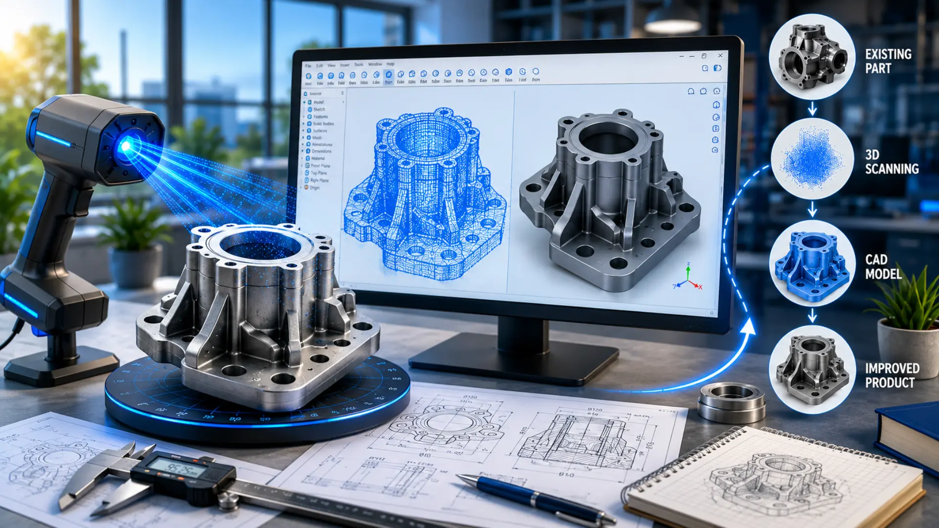
Geomagic Reverse Engineering is one of the most highly trusted solutions adopted by engineers today to convert physical parts into accurate digital models for manufacturing and product development. In addition, 3D Reverse Engineering enables engineers to scan existing products with advanced scanning technology and capture the shape, size, and features exactly as they are.

These software solutions that transforms a scanned physical object into an accurate 3D CAD model. This technology is used by engineers to reproduce existing items, create engineering drawings, and design models for manufacturing or redesign.

What Is Geomagic Reverse Engineering?

It is a software-based solution that transforms a scanned physical object into an accurate 3D CAD model. This technology is used by engineers to reproduce existing items, create engineering drawings, and design models for manufacture or redesign.

This software can import data from 3D scanners and convert it to CAD files that can be edited, analyzed, and applied to future production.

It is commonly used for:

  • CAD model creation
  • Product redesign
  • Part recreation
  • Quality inspection
  • Prototype development
  • Manufacturing documentation
  • Design improvement
  • Legacy part replacement

What Is 3D Reverse Engineering?

It’s a technique that uses 3D scanning technology to capture the exact size and shape of an already existing product. The data is then scanned and turned into a digital model that engineers can manipulate, enhance, and manufacture.

Engineers can quickly and easily develop very accurate digital models to help with product development and manufacturing, rather than having to measure each feature manually.

This process can be applied when:

  • Original CAD files are not available.
  • Replacement parts need to be recreated.
  • Existing products require improvement.
  • Older equipment should be maintained.
  • Evaluation of product performance.
  • Why Is Reverse Engineering Important in Product Development?

If a company has already designed a product, they may choose to refine it instead. Reverse engineering facilitates this process in a much faster and more efficient manner.

Recreate Old Parts

Several older products do not have original drawings or CAD files. Reverse Engineering is used to produce an accurate digital model of an existing part, which makes manufacturing so much more convenient in the future.

Improve Existing Designs

Through studying products and identifying areas of weakness, engineers can make improvements to make the products better, stronger, and more functional.

Develop Better Replacement Parts

If original parts are unavailable, reverse engineering can be used to develop a proper and exact replacement part.

Speed Up Product Development

Digital models can be used to make design changes without having to redraw the original design from scratch, thereby saving development time.
How Does Geomagic Reverse Engineering Improve Product Development?

Accurate digital data is essential for modern manufacturing, and Geomagic Reverse Engineering helps simplify the process.

Creates Accurate CAD Models

The software can scan parts and convert them into accurate CAD models for design changes and production.

Reduces Manual Work

Engineers can scan a component and produce accurate digital models faster than taking measurements by hand.

Supports faster design changes

Digital CAD files allow you to edit products, test product improvements, and create new designs for production with ease.

Improves Product Quality

Accurate digital models decrease manufacturing mistakes and assist in creating better products.

Saves Time and Cost

This helps to streamline the design and documentation process, which can save engineering time and decrease the total development cost for businesses.

Benefits of 3D Reverse Engineering

The 3D Reverse Engineering technique has numerous benefits for manufacturers in various industries.

Better Accuracy

High-precision advanced scanning technology captures detailed product information.

Faster Engineering Process

Scanned parts can be modeled digitally in a much faster time than by manual measurement.

Easier Product Improvements

Digital models can be altered and optimized without having to design it over again.

Better Documentation

CAD files and engineering drawings ensure easy future manufacturing and maintenance.

Reduced Manufacturing Errors

Accurate digital models enhance production quality and minimize expensive errors.
Industries That Use Reverse Engineering

Industries that demand precision and reliable product development make use of reverse engineering.

Automotive Industry

Vehicle components are reproduced and enhanced to achieve better performance.

Aerospace Industry

Advanced scanning technology is used to recreate and inspect complex aircraft parts.

Industrial Equipment Manufacturing

Older machine parts are reproduced to increase equipment life and reduce maintenance.

Medical Device Manufacturing

Accurate instruments and custom components are developed by medical companies using reverse engineering.

Consumer Product Manufacturing

Manufacturers enhance product designs while minimizing product development time.
Best Practices for Successful Reverse Engineering

Organizations can do better by following a systematic engineering procedure.

Use High-Quality 3D Scanners

Reliable digital models are developed with accurate scanning.

Verify CAD Models

Digital models should be validated by engineers before manufacturing.

Work with Experienced Engineers

More accurate models and documentation are created by professional engineering teams.

Follow Industry Standards

Engineering files should follow international standards like ANSI, ISO, DIN, ASME, BS, and JIS.

Regularly update Digital Files

Having precise CAD files helps with future product improvements and maintenance.
Choosing the Right Reverse Engineering Partner

When it comes to product development, it’s crucial to choose an experienced engineering company.

Look for a provider with:

  • Advanced scanning technology.
  • CAD modelling expertise.
  • Product development experience.
  • Strong quality control.
  • Industry-standard documentation.
  • Reliable technical support.

A good engineering partner can assist the business to duplicate products, enhance designs, and streamline production procedures.

Conclusion

Today’s product development relies on model accuracy and efficient engineering processes. Businesses can use Geomagic Reverse Engineering to reconstruct and enhance existing products and build accurate CAD models for manufacturing.

In combination with 3D Reverse Engineering, these technologies enable manufacturers to limit development time, enhance product quality, and facilitate quicker innovation in diverse industrial sectors.

Keyways provides engineering solutions for product development and manufacturing industries. Connect with Keyways on LinkedIn to explore their latest engineering insights, reverse engineering expertise, and innovative manufacturing solutions.

Why Every Product Needs Design for Manufacturing Before Production?

Creating a great design is just the beginning of bringing a new product to market. The product should also be easy, affordable, and meet quality requirements. While many businesses are concerned with the product design, they tend to forget the manufacturing process, and this can cause production delays, increase costs, and make it necessary to change the design unnecessarily. This is why Design for Manufacturing is an important step before production begins.

Planning a product with manufacturing in mind can ease manufacturing, minimize material waste, and enhance product quality. Sheet Metal Design Service is also important in many industries as it helps engineers to design components that are easier to fabricate, assemble, and manufacture with more accuracy.

What Is Design for Manufacturing(DFM)?

DFM is an engineering method that aims to design cost-effective, simple, and efficient products. Rather than making changes to the manufacturing process to accommodate the design, it makes sure that the design is optimized to allow for efficient manufacturing.

To lower production costs, enhance product quality, decrease manufacturing time, and prevent manufacturing issues during the production phase.

DFM takes into account factors such as:

  • Material selection
  • Manufacturing methods
  • Part complexity
  • Assembly process
  • Production costs
  • Product quality
  • Standard components
  • Ease of maintenance

Why Is Design for Manufacturing Important?

Many production issues occur due to a lack of consideration of product design for the manufacturing aspect. Quality changes during manufacturing can cause manufacturing and delivery delays.

Here are reasons why DFM is so important:

Reduces Manufacturing Costs

Efficient manufacturing means fewer production steps, less machine time, and less material needed for the products. This reduces the manufacturing costs overall.

Improves Product Quality

Simple and practical designs are easier to manufacture accurately, resulting in high-quality products and lower defect rates.

Speeds Up Production

If products are designed properly from the start, manufacturers can create them more rapidly with less downtime.

Reduces Material Waste

Optimized designs ensure the material is used efficiently, which helps businesses save on waste and production costs.
How Does DFM Improve Production?

Good planning is the key to successful manufacturing. By recognizing production issues early, businesses are better able to enhance product designs before production begins.

Simplifies Product Design

Simple design is easier to make, check out, and join. Simplicity increases production efficiency.

Improves Material Selection

Selecting the right materials enables to lower production costs while keeping product strength and durability.

Makes Assembly Easier

Products with fewer parts and an easier assembly process will save labor time and increase production speed.

Reduces Design Changes

Early identification of possible manufacturing issues saves on post-manufacturing modification costs.

Backs Better Quality Control

Manufacturing products are more easily inspected, and the quality is more consistently maintained in manufacturing.

Role of Sheet Metal Design Service

Sheet metal parts are a product used by many industries. A professional Sheet Metal Design Service helps design parts that are easy to manufacture while maintaining strength, accuracy, and product quality through professional engineering solutions.

A well-designed sheet metal part increases the efficiency of the production process and minimizes manufacturing issues.

It includes:

  • Part design
  • Bend allowance calculations
  • Flat pattern development
  • Hole and slot placement
  • Material optimization
  • Manufacturing drawings
  • Assembly support
  • Production documentation
  • Benefits of Sheet Metal Design Service

Professional engineering support can help manufacture to improve design accuracy, ease the manufacturing process, and reduce manufacturing costs.

Better Manufacturing Accuracy

Proper parts design allows for the correct assembly and minimizes production errors.

Lower Material Costs

Optimized layouts help reduce scrap material and improve material usage.

Faster Fabrication

Faster cutting, bending, and assembly of simple designs.

Improved Product Performance

Optimally designed sheet metal components enhance product strength, durability and reliability.

Easier Production Planning

Good drawings and accurate specifications assist manufacturers in planning their production.
Industries That Benefit from DFM

DFM is employed in many industries for enhancing product quality and production efficiency.

Automotive Industry

DFM is utilized by vehicle manufacturers to minimize production costs and enhance quality and performance.

Aerospace Industry

The design of aircraft parts must be precise and adhere to strict manufacturing standards.

Industrial Equipment Manufacturing

Industrial machinery manufacturers use DFM to achieve efficient production and lower maintenance expenses.

Electronics Industry

The design of electronic products must be accurate, and the efficiency of assembly and reliability must be high.

Medical Equipment Manufacturing

Medical devices should be manufactured with ease and be of a high quality.
Best Practices for Successful Manufacturing Design

By using known manufacturing design principles, businesses can get better results.

Keep Designs Simple

Simple products are easier and less expensive to manufacture.

Use Standard Components

Standard parts lower production costs and increase product availability.

Select Suitable Materials

Select materials for strength, cost, and manufacturing needs.

Communicate and cooperate with Manufacturing Experts.

Designers can work together with manufacturers to address production issues in the early stages of the design process.

Choosing the Right Engineering Partner

Selecting an experienced engineering company is essential for successful product development.

Look for a partner that offers:

  • Manufacturing expertise
  • CAD design capabilities
  • Product optimization
  • Sheet metal engineering experience
  • Industry-standard documentation
  • Strong quality control
  • Reliable technical support

An experienced engineering partner can assist companies in lowering manufacturing risks and enhancing manufacturing efficiency.

Conclusion

Smart planning is the basis for success in developing products. A good manufacturing approach can help enterprises to lower production costs, enhance product quality, ease production, and prevent product redesign in the process of production. This enables companies to design products with ease in manufacturing, assembly, and delivery and still meet quality and performance specifications.

Keyways provides engineering and manufacturing solutions for product development across various industries. Connect with Keyways on LinkedIn to explore their latest engineering insights, manufacturing expertise, and innovative design solutions.

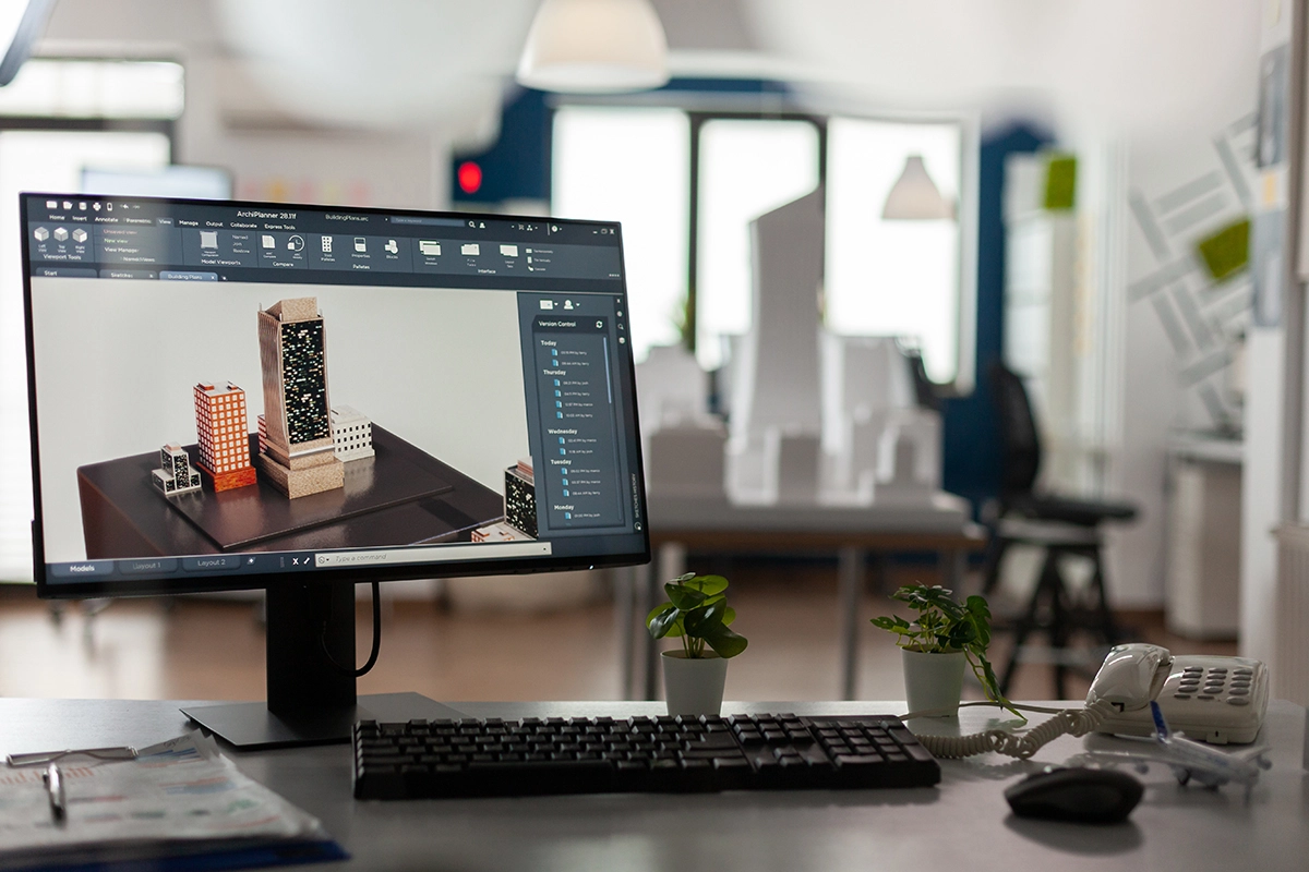
The Complete Guide to 3D Architectural Rendering Services That Improve Design Accuracy

In today’s architectural and construction realm, more than just technical drawings and floor plans are necessary. Clients, architects, and developers are looking to see a realistic view of the building before any construction work is done. Clear visualizations help to grasp design concepts, pinpoint problems, and make decisions early in the development process. This is the reason why 3D Architectural Rendering Services are an integral part of modern-day architectural design and planning.

Using advanced visualization technology, architects can generate realistic images that truly represent buildings, interiors, and space outdoors before construction. By using Photorealistic Rendering Services, designers can present materials, lighting, textures, and landscaping in great detail, giving their clients the confidence they desire in their final design and minimizing the risk of unexpected design changes later in the process.

What Are 3D Architectural Rendering Services?

This service involves creating realistic digital images of buildings and architectural designs using specialized 3D software. These renderings are essential to providing clients, architects, and builders with a clear picture of what their project will look like once built.

Unlike traditional 2D drawings, 3D renderings provide realistic views from different angles, making it easier to understand the overall design.

These services are commonly used for:

  • Residential buildings
  • Commercial projects
  • Office spaces
  • Interior design
  • Exterior design
  • Landscape planning
  • Real estate marketing
  • Construction presentations

Once the construction phase begins, businesses can enhance communication and minimize design errors by creating realistic visuals in advance.

Why Design Accuracy Matters?

Crafting and planning are essential in each construction project. Mistakes in design can cost, slow construction, and impact the final product, even if it’s a minor design flaw.

Proper design can benefit businesses in the following ways:

Reduce Construction Errors

Detailed visualisations can help pinpoint design problems before the works commence and save costly changes later in the construction process.

Improve Client Understanding

Technical drawings are hard to comprehend for many clients. Realistic renderings help them to see the finished product.

Speed Up Decision-Making

Clients can easily see the design, and they can approve the layout, materials, and finishes faster.

Improve Team Communication

This visual reference can be used by architects, engineers, contractors, and clients, minimizing confusion throughout the process.

How Do 3D Architectural Rendering Services Improve Design Accuracy?

Digital visualization is a valuable tool in modern architectural projects. These services are used in order to design teams to create accurate presentations of the project to minimize errors during planning and construction.

Better Design Visualization

Realistic renders depict all elements of a structure, such as walls, windows, lighting, materials, furniture, and outdoor areas. This allows everyone to get a sense of the design before starting work.

Early Problem Detection

Architects can anticipate design dilemmas, layout issues, or space constraints before construction. Preventing problems early is time- and cost-saving.

Easier Design Changes

Digital models enable architects to quickly make changes without having to recreate the entire design. Clients can compare and evaluate options, and select the option that is most suitable for them.

Improved Project Approval

Efficiently communicating the project to the client through visual presentation helps to expedite and optimize the approval process.

Better Marketing Presentations

Detailed and coherent renderings can also help to market home and business initiatives before construction.

Role of Photorealistic Rendering Services

Photorealistic Rendering Services offer architectural visualization to a higher level, producing images that can be close to actual photographs. The lighting, shadows, reflections, texture, and materials in these renderings are realistic, and the client gets a realistic idea of how the final project will look.

Photorealistic renderings can include:

  • Natural lighting effects
  • Interior furniture layouts
  • Exterior landscaping
  • Building materials
  • Glass reflections
  • Surface textures
  • Environmental surroundings
  • Day and night views
  • Benefits of Architectural Rendering

There are many benefits that architects, builders, developers, and property owners can have by using professional rendering services.

Better Client Communication

Visual presentations aid clients in grasping concepts without technical expertise.

Reduced Design Revisions

Potential problems can be detected and addressed before construction is underway.

Faster Project Completion

Straightforward designs minimize misunderstanding and changeovers.

Improved Design Quality

Architects can experiment with various layouts, colors, materials, and finishes before settling on the final design.

Cost Savings

Early identification of design issues can minimize construction expenses and avoid unnecessary material waste.

Industries That Use Rendering Services

Architectural visualization is used in a variety of industries.

Residential Construction

Drawings are used by builders to show buyers houses, apartments, and housing projects.

Commercial Buildings

Realistic presentations of projects are useful in office buildings, shopping centers, and business premises.

Interior Design

Realistic images are used by interior designers to promote the room layout, lighting, colors, and furniture.

Real Estate

Renderings are used by developers to sell properties before they are actually built.

Hospitality Industry

Architectural visualization is used by hotels, restaurants, and resorts to showcase design ideas to investors and clients.

Tips for Getting the Best Rendering Results

Businesses should keep a few things in mind to create high-quality architectural renderings.

Provide Complete Project Information

Realistic renderings are created with accurate drawings and design details.

Choose High-Quality Materials

Realistic textures and finishes enhance the final appearance.

Include Proper Lighting

The overall appearance of the design is greatly influenced by natural and artificial lighting.

Review Before Final Approval

When reviewing renderings, it is important to notice if any modifications are required before construction.

Work with Experienced Professionals

A professional rendering expert has an idea of the architectural standards and produces accurate visual presentations.

Conclusion

Accurate visualization is an important part of every successful architectural project. 3D Architectural Rendering Services benefit architects, builders, and developers by providing a clear visualization of the project, minimizing planning mistakes, and ensuring accurate construction. When paired with Photorealistic Rendering Services, businesses can enhance communication, streamline approval processes, and achieve better project results.

Keyways offers engineering and visualization solutions to the Architecture, Construction, and Product Development sectors. Connect with Keyways on LinkedIn to explore their latest design innovations, rendering expertise, and engineering insights.

How Reverse Engineering Tools Mechanical Improve Product Development

Product teams face constant pressure to launch faster, cut costs, and fix design flaws before they reach the market. Reverse engineering gives engineers a practical way to meet all three goals at once. By scanning an existing part, mechanical teams rebuild accurate digital models, study hidden geometry, and improve designs without starting from zero. Companies that offer professional Reverse Engineering Services help manufacturers turn physical parts into usable CAD data quickly. This process saves time, reduces guesswork, and gives engineers a solid foundation to build better products.

What Is Reverse Engineering in Mechanical Design?

Reverse engineering means taking an existing physical object and working backward to understand how it was built. Engineers scan the part, capture its exact shape, and convert that data into a 3D CAD model. This model shows dimensions, tolerances, and material properties that the original design files may have lost or never had. Mechanical teams use this approach when original drawings go missing, when a supplier discontinues a part, or when they need to improve an outdated design. Instead of measuring every surface by hand, engineers rely on digital tools to capture accurate data within hours instead of weeks.

The Data: What Reverse Engineering Actually Delivers

The time and cost savings from scan-based reverse engineering aren’t just anecdotal – they show up clearly in vendor benchmarks and case studies:

  • 3D scanning can reduce the analysis and design validation portion of reverse engineering by up to 80% compared with traditional manual measurement methods (FARO).
  • One documented case of a manufacturer and distributor of construction machine spare parts saved 85% in time and cost after switching to scanner-based reverse engineering instead of manual measurement.
  • A process that once took multiple days of manual measurement and drafting can now be completed through a scan-to-CAD workflow in roughly 2 to 8 hours, including scan setup, processing, and export.
  • Modern 3D scanners capture geometry with accuracy down to 0.02–0.05 mm, which is precise enough for most mechanical and industrial tolerance requirements, including aerospace and medical applications.

At a glance:

MetricReported ImprovementSource
Analysis & validation time cutUp to 80%FARO
Time & cost savings (case study)85%Industry case data
Manual measurement vs. scan-to-CADMulti-day → 2–8 hrsScan-to-CAD workflow benchmarks
Scanning accuracy0.02–0.05 mm3D scanner manufacturer specs

Why Manufacturers Turn to Reverse Engineering Tools

Manufacturers face several problems that reverse engineering solves directly. Old machines often run on parts that no longer exist in any catalog. Some parts changed hands between companies so many times that nobody kept the original specifications. In other cases, a competitor’s product performs better, and the team wants to understand why. Reverse engineering tools give engineers a way to answer these questions without disrupting production. Scanning technology captures every curve and surface with precision, so teams can recreate a part or redesign it entirely. This approach also helps companies avoid expensive downtime, since they can produce a replacement part fast instead of waiting weeks for a new order from an original supplier.

Core Reverse Engineering Tools Mechanical Teams Rely On

Modern shops use several types of Reverse Engineering Tools Mechanical teams need to capture and rebuild parts. 3D laser scanners create detailed point clouds that map every surface of an object. Structured light scanners work well for smaller, more detailed components that need tighter tolerances. Coordinate measuring machines check dimensional accuracy once a scan is complete. CAD software then converts raw scan data into usable solid models that engineers can edit, test, and refine. Some teams also use CT scanning to capture internal geometry without cutting a part open. Together, these tools give mechanical engineers a complete picture of a component, inside and out, so they can validate designs, spot flaws, and move confidently into production.

How These Tools Speed Up Product Development

Faster Prototyping

Engineers no longer wait weeks for hand-drawn measurements or trial-and-error sketches. A scan captures a part’s geometry in minutes, and CAD software turns that data into a working model the same day. Teams then send this model straight to 3D printing or CNC machining for a physical prototype. This shortens the gap between an idea and a testable product. Teams catch design problems earlier, before those problems become expensive mistakes on the production line.

Fewer Design Errors

Manual measurements introduce errors, especially on complex or curved surfaces. Scanning tools remove much of that risk because they capture geometry directly from the physical part. Engineers compare the digital model against the original design specification, and they catch mismatches immediately. This level of accuracy matters most in industries like aerospace and medical devices, where a small tolerance error can cause a serious failure. Reverse engineering gives teams confidence that their models match reality, not just their assumptions.

Better Collaboration Across Teams

A shared 3D model gives every department something concrete to review. Design, manufacturing, and quality teams can look at the same file and flag issues before production starts. This shared visibility cuts down on miscommunication and reduces the number of revision cycles a product goes through. When everyone works from the same accurate data, decisions happen faster. Teams spend less time correcting mistakes that a clearer model could have prevented earlier.

Missing the CAD files for a critical part?

KEYWAY’s engineering team can scan and rebuild it into a manufacturing-ready model. Explore our reverse engineering services to get started.

Quality Control and Validation

Reverse engineering does not stop once the scan finishes. Engineers still need to check the new model against real-world requirements before anyone approves it for production. Quality teams compare the digital file to functional tolerances, load requirements, and material specifications. They run the model through KEYWAY’s simulation services to test how the part behaves under stress, heat, or repeated use. This validation step catches problems early, long before a company spends money on tooling or a full production run. It also gives teams documented proof that the new part matches or exceeds the performance of the original, which matters for regulated industries that require detailed records.

Time and Cost Savings You Can Measure

Reverse engineering saves real money once you look at the numbers. Traditional design from scratch can take weeks of measuring, drafting, and testing. Scanning a part and converting it into CAD data often takes just a few days. This shorter timeline lowers labor costs and gets products to market sooner. Companies also avoid the cost of ordering new tooling for parts that already exist somewhere in their history. Instead of building a mold or fixture from zero, engineers pull accurate data from the original part and adjust the design where needed. Over a full project, these savings add up, especially for companies that repeat this process across multiple product lines each year.

Common Applications Across Industries

Reverse engineering supports a wide range of industries today. Automotive teams use it to recreate discontinued parts for classic or specialty vehicles. Aerospace companies rely on it to maintain aging aircraft components that no longer have active suppliers. Medical device makers use scanning tools to design custom implants and prosthetics that fit a patient’s exact anatomy. Industrial equipment manufacturers turn to reverse engineering when a machine breaks down and the original part is no longer available anywhere. Consumer product companies also study competitor designs to find opportunities for improvement. Our related guide on how 3D reverse engineering recreates parts without original CAD files walks through this exact scenario in more detail. Across every one of these industries, the same principle applies: accurate digital data leads to faster decisions and stronger products.

Choosing the Right Reverse Engineering Partner

Not every company has the equipment or expertise to handle reverse engineering in-house. Scanning hardware costs a significant amount, and the software requires real training to use well. Many manufacturers choose to work with an outside partner instead of building this capability internally. A strong partner brings experienced engineers, calibrated scanning equipment, and a proven process for turning physical parts into usable CAD files. Before choosing a provider, ask about their scanning accuracy, turnaround time, and experience with your specific industry. The right partner will also communicate clearly throughout the project and walk you through each stage, from the initial scan to the final validated model, so your team knows exactly what to expect.

Signs Your Team Needs Reverse Engineering

Some warning signs make the case for reverse engineering fairly obvious. A supplier may go out of business and leave you without a source for a critical part. Original CAD files may get lost after years of software changes or staff turnover. A part might fail in the field, and your team needs to understand exactly why before it happens again. You might also want to upgrade an old design with better materials or tighter tolerances, but nobody kept the original specifications. Any of these situations points to the same solution. Scanning the physical part and rebuilding it digitally gives your team a clear starting point instead of guesswork.

Final Thoughts

Reverse engineering has become a practical, everyday tool for mechanical product development, not a niche technique reserved for special cases. It helps engineers rebuild lost designs, fix broken parts, and improve products faster than traditional methods allow. Companies that adopt these tools gain a real advantage: shorter development cycles, fewer errors, and stronger final products. Sharing reverse engineering insights on LinkedIn can also help engineering professionals stay updated on industry trends, tools, and best practices.

KEYWAY works with manufacturers across industries to deliver accurate scanning, modeling, and design support for projects of any size.

Common Design Challenges Solved with Professional CAD Drafting Service

Every design team runs into the same wall at some point. Deadlines shrink, drawings pile up, and small errors turn into expensive delays. A reliable CAD Drafting Service fixes this problem at the root by giving teams accurate, ready-to-use drawings without the usual back and forth. Instead of chasing revisions or fixing mistakes late in the process, engineers and architects get clean, error-free files that move projects forward. This article looks at the most common design challenges companies face and how professional drafting support solves each one.


Why Design Challenges Slow Down Projects

Design problems rarely show up all at once. They creep in through small errors, missed details, or drawings that do not match the final build. A single wrong measurement can delay a project by weeks. Poor communication between departments can send a design in the wrong direction before anyone notices.

Most of these issues trace back to one root cause: drafting work that was rushed, handled by inexperienced staff, or done without the right software knowledge. Professional drafting teams solve this by bringing structure, consistency, and technical skill to every drawing they touch.

Design teams also feel pressure from tighter budgets and shorter timelines. Clients expect fast turnaround without sacrificing accuracy, and that combination is hard to deliver without dedicated drafting support. When drafting sits on the side desk of an already busy engineer, quality naturally drops. This happens not because the engineer lacks skill, but because drafting requires focused attention that a packed schedule rarely allows.

Inaccurate Measurements and Dimensioning Errors

Dimensioning mistakes cause more project delays than almost anything else. A missed decimal point or an incorrect tolerance can force an entire batch of parts to be scrapped. Manufacturing teams then lose time reordering materials and rescheduling production.

Skilled drafters check every dimension against design intent and manufacturing standards. They catch errors before drawings reach the shop floor, which protects both budget and schedule. This level of accuracy is hard to maintain in-house when staff juggle multiple projects at once.

The Cost of Small Errors

A single dimensioning error can ripple through an entire supply chain. Vendors quote based on drawings, so any inaccuracy leads to wrong material orders, wasted machining time, and frustrated clients. Professional drafters build in quality checks at every stage, so these errors get caught early instead of after production has already started.

Miscommunication Between Design and Engineering Teams

Design intent often gets lost between the person who sketches an idea and the engineer who has to build it. Sketches on a napkin or vague verbal instructions leave too much room for interpretation. When drawings are unclear, engineers guess, and guessing leads to rework.

A professional CAD drafting service closes this gap. Drafters translate rough concepts into precise, standardized drawings that both design and engineering teams can read the same way. Clear callouts, proper layering, and consistent formatting remove the guesswork, so everyone works from the same source of truth.

Slow and Inconsistent Manual Drafting

Manual drafting, or even basic in-house CAD work without dedicated specialists, tends to be slow. Drawings pile up because staff are pulled between design tasks, client meetings, and drafting duties. Deadlines slip, and quality suffers when people rush to catch up.

Outsourced drafting teams work faster because drafting is their only focus. They know the shortcuts, templates, and workflows that shave hours off every drawing set. This speed does not come at the cost of quality since experienced drafters still follow strict review processes before sending files back to the client.

Converting Rough Concepts into Precise 2D and 3D Models

Turning a rough sketch or an old paper drawing into a usable digital model is one of the toughest parts of any design project. Many companies still have legacy drawings from decades ago that need to be rebuilt from scratch. Doing this correctly requires both drafting skill and deep software knowledge.

This is where 2D Drafting in Solidworks becomes valuable. Solidworks allows drafters to build precise, editable 2D layouts that later feed into 3D modeling, simulation, and manufacturing workflows. A professional team can take a hand sketch, an outdated blueprint, or a rough concept and turn it into a fully dimensioned, production-ready drawing within days rather than weeks.

Legacy Drawing Conversion

Older companies often store decades of paper drawings or scanned PDFs with no editable source files. When a design needs updating, someone has to redraw it from scratch. Professional drafters specialize in this kind of conversion work. They rebuild legacy drawings into modern CAD formats while preserving original dimensions and design intent, so nothing gets lost in translation.

Maintaining Design Standards Across Multiple Projects

Companies that run several projects at once often struggle to keep drafting standards consistent. One project might use a different layer naming convention than another. Title blocks, line weights, and annotation styles can vary from drawing to drawing, which creates confusion when files move between teams or contractors.

A dedicated drafting service applies the same standards across every project. Templates, naming conventions, and quality checklists stay consistent no matter how many drawings pass through the pipeline. This consistency matters most when drawings need to be shared with outside vendors, contractors, or regulatory bodies that expect a certain format.

Scaling Drafting Work for Complex or Large Projects

Large projects generate huge volumes of drawings in short windows. An in-house team sized for normal workloads gets overwhelmed the moment a big project lands. Hiring temporary staff takes time, and training them on internal standards takes even longer.

Outsourced drafting teams scale up or down based on project needs. A company can send a large batch of drawings during a busy season and scale back once the workload normalizes. This flexibility saves money compared to maintaining a large in-house team year-round, and it keeps quality steady even when volume spikes.

Seasonal industries feel this benefit the most. Construction firms often see a surge of bids in spring, while manufacturers may face a rush of orders around new product launches. Building an in-house team large enough to handle peak demand means paying for idle capacity during slower months. A flexible drafting partner removes that trade-off entirely, since companies only pay for the work they actually need.

Choosing the Right Drafting Partner

Not every drafting provider delivers the same level of quality. Some outsource work to junior staff with little oversight, which brings back the same errors a company was trying to avoid. Others lack experience with specific industries, so drawings miss requirements that matter for manufacturing, construction, or compliance.

Before hiring a drafting partner, teams should ask a few direct questions. Does the provider have experience in the relevant industry? Do they offer revision support after delivery? Can they handle both new designs and legacy drawing conversions? A provider that answers yes to all three saves companies from switching vendors mid-project.

Software compatibility matters as well. A provider fluent in the same CAD platforms a company already uses avoids file conversion issues and keeps drawings editable on both ends. This small detail prevents a surprising number of headaches later in the project.

How Professional Drafting Solves These Problems Together

Each challenge listed above connects to the next. Poor communication leads to dimensioning errors. Inconsistent standards make legacy conversions harder. Slow manual processes make scaling nearly impossible. A professional drafting partner addresses all of these issues at once rather than patching them one at a time.

Experienced drafters bring standardized workflows, software expertise, and quality control checks that in-house teams often cannot maintain alongside their regular workload. The result is fewer errors, faster turnaround, and drawings that hold up through manufacturing, construction, or regulatory review.

Companies that adopt professional drafting support also free up their engineers and designers to focus on higher-value work. Instead of spending hours on repetitive drawing tasks, internal teams can concentrate on innovation, problem solving, and client relationships while drafting specialists handle the technical documentation.

Final Thoughts

Design challenges are a normal part of any project, but they do not have to slow things down. Dimensioning errors, miscommunication, slow manual work, inconsistent standards, and scaling problems all have one common solution: bringing in a team that specializes in drafting.

KEYWAY works with companies across industries to solve exactly these problems, combining technical drafting skill with fast turnaround and consistent quality. Whether a project needs legacy drawing conversion, precise 2D layouts, or full-scale drafting support for a complex build, the right partner makes the difference between a project that stalls and one that ships on time. For updates, project examples, and industry insights, follow along on LinkedIn.

Understanding Inventor CAM Service and Its Benefits for Manufacturers

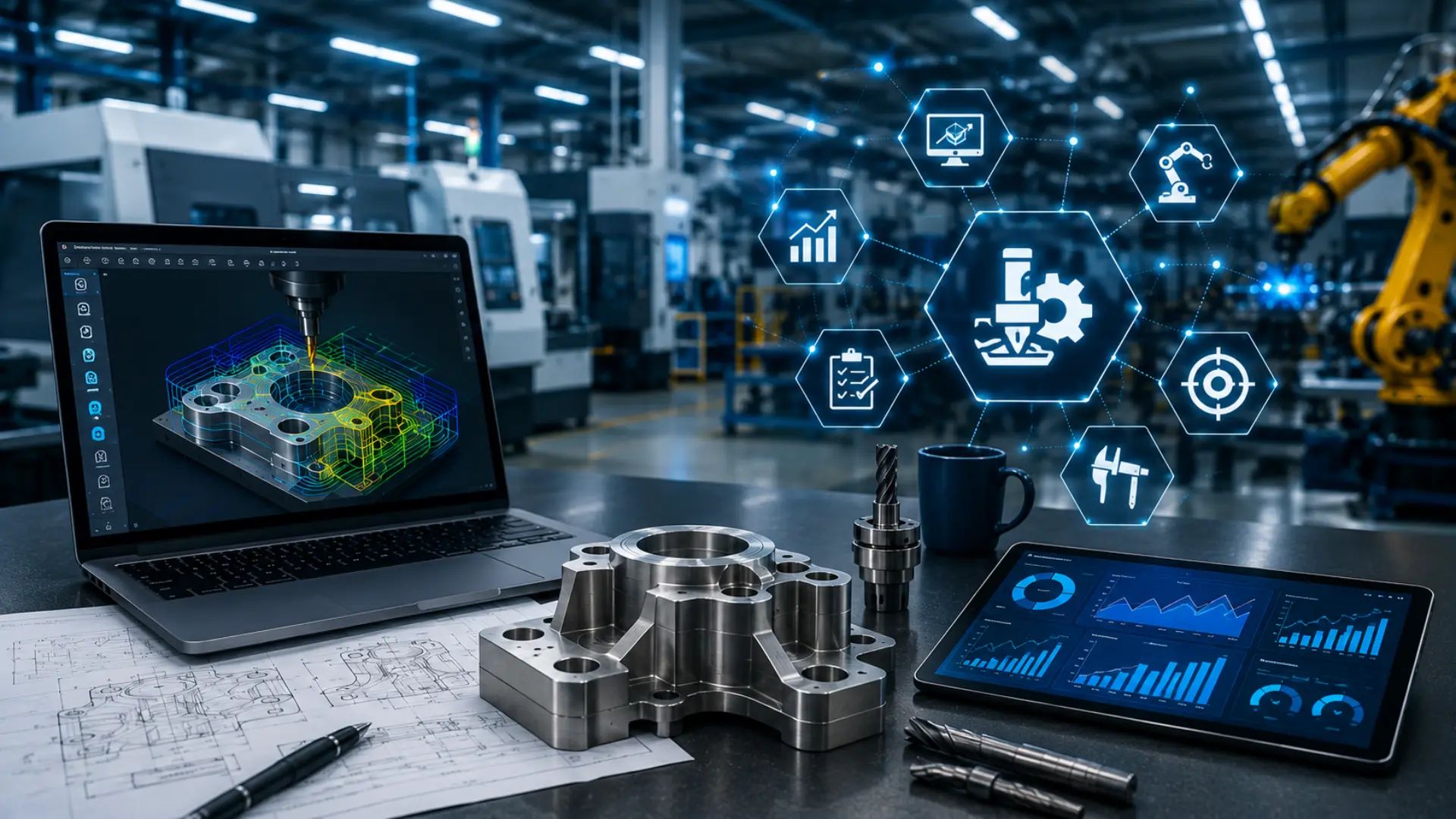
Manufacturing teams face constant pressure to deliver parts faster without sacrificing quality. An Inventor CAM Service gives engineers a direct path from 3D design to machine-ready toolpaths, all inside one familiar workspace. This article explains what the service does and why manufacturers rely on it. It also shows how the right setup cuts costs and speeds up production, whether you run a small job shop or a large production floor.

What Is Inventor CAM Service?

Inventor CAM Service is a manufacturing tool built directly into Autodesk Inventor. Engineers move from design to machining without exporting files to a separate program. The software reads native Inventor models, so any design change updates the toolpath automatically. This tight connection between design and manufacturing removes a common source of shop floor errors.

Teams using CAM Service can programme mills, lathes, and multi-axis machines from a single workspace. The platform supports 2.5-axis, 3-axis, and 5-axis milling, along with turning operations. Because everything lives inside Inventor, operators skip the file conversion step that often causes lost data or broken geometry. More than 70% of advanced manufacturing facilities worldwide now use some form of integrated CAM software for their CNC operations.

Why CAM Service Matters for Modern Manufacturers

Manufacturers face steady pressure to deliver parts faster and at lower cost. Skilled machinists remain hard to find – U.S. manufacturing had roughly 495,000 job openings as of January 2026, up 11% year-over-year, with CNC programmers and machinists among the hardest roles to fill. Customers expect shorter lead times each year. A strong CAM Service addresses these pressures head-on.

The software cuts programming time through associative models. When a part changes, the CAM strategy updates instead of restarting from scratch. This single feature saves hours during every revision cycle, especially on complex assemblies with frequent design tweaks.

Quality improves too. Built-in simulation catches collisions and programming errors before a machine ever runs a part. Shops that add toolpath simulation and verification before cutting commonly report scrap rate reductions of up to 30%. Fewer surprises on the floor also mean operators spend less time troubleshooting and more time producing finished parts.

Customer expectations keep rising as well. Buyers want shorter lead times, tighter tolerances, and lower prices all at once. Manufacturers stuck with outdated, disconnected workflows struggle to meet these demands. Shops using an integrated CAM Service adjust and deliver much faster.

Inventor CAM Service: The Data

The advantages of integrated CAM aren’t just anecdotal. Here’s what current industry benchmarking shows:

30–50%

Reduction in CNC programming time from automated, associative CAM workflows versus manual re-programming.

Source: Business Research Insights, CAM Software Market Report (2026)

Up to 75%

Programming time reduction AI-assisted CAM can deliver on complex, multi-axis parts, versus building strategies from scratch.

Source: Dassault Systèmes / manufacturing AI benchmarks (2026)

495,000

U.S. manufacturing job openings as of January 2026 — up 11% year-over-year, with machinists and programmers among the hardest roles to fill.

Source: U.S. Bureau of Labor Statistics, JOLTS

Up to 30%

Typical cut in scrap rate when shops add toolpath simulation and verification before parts reach the machine.

Source: CNC machining industry benchmarks (2025–2026)

Programming Time Saved, by Part Complexity

The more complex the part, the more an integrated, associative CAM workflow pays off:

Standard 2.5–3 axis parts
30–50% faster programming
Complex multi-axis / 5-axis parts
40–75% faster programming


Curious how much programming time your shop could get back?

Explore Inventor CAM Service with KEYWAY →


Key Benefits of Inventor CAM Service for Manufacturers

The advantages of adopting CAM Service extend across design, production, and cost management. Manufacturers notice these benefits first.

Faster Programming and Shorter Lead Times

The associative link between design and toolpath removes duplicate work. Programmers build a strategy once, and updates happen automatically as the design evolves. Shops report shorter turnaround on both prototypes and production runs, which helps teams meet tight customer deadlines without adding staff.

Fewer Errors on the Shop Floor

Built-in simulation displays the full machining sequence before it reaches the machine. Operators catch tool collisions, incorrect feeds, and gouges early in the process. This visibility reduces scrap rates and keeps machines running instead of sitting idle for rework.

Stronger Collaboration Across Teams

Design and manufacturing teams work inside the same file. Engineers no longer wait for a separate CAM department to translate their model into a toolpath. Everyone views the same data, which speeds up communication and reduces miscommunication between departments.

Support for Complex Geometry

Multi-axis machining strategies handle complex parts that older systems struggle to process. Aerospace, medical device, and precision tooling manufacturers benefit most from this capability. Their parts often carry tight tolerances and unusual shapes that demand careful toolpath planning.

Lower Overall Production Costs

Combining design and CAM into a single platform cuts software licensing costs. Teams also spend less time training staff across multiple systems. Over time, these savings accumulate across a shop’s entire operation, freeing up budget for new equipment or additional projects.

Industries That Rely on CAM Service

Different industries lean on CAM Service for different reasons, but the core advantage stays the same: faster, more accurate machining with fewer errors.

Aerospace and Defense

Aerospace parts often carry tight tolerances and complex curved surfaces. CAM Service handles these shapes through multi-axis toolpaths that keep accuracy high while cutting programming time. Defense contractors also value the simulation step, since it catches mistakes before expensive raw material gets machined.

Medical Device Manufacturing

Medical components demand precision down to fractions of a millimetre. CAM Service supports the small, intricate toolpaths these parts require. The associative design link also helps teams respond quickly when a revision arrives mid-production.

Automotive and Industrial Tooling

Tooling manufacturers produce moulds, dies, and fixtures with detailed surfaces. CAM Service speeds up this work through reusable machining templates, so programmers do not rebuild strategies from scratch for every similar job.

Common Challenges Manufacturers Face Without CAM Service

Shops that rely on separate design and CAM software often run into avoidable problems. File conversion between systems can corrupt geometry or strip out design details, forcing programmers to rework models by hand.

Version control also becomes difficult. When a design changes, someone has to update the CAM file separately. This manual step often gets missed under deadline pressure. The result is a part machined from outdated data, which leads to scrap and delays.

Training adds another layer of difficulty. Staff who juggle multiple software platforms need more time to become proficient, and mistakes happen more often during the learning curve. An integrated CAM Service removes these friction points by keeping design and manufacturing in one connected environment.

Getting Started with Inventor CAM Service

Manufacturers considering CAM Service should start by reviewing their current parts and machines. Identify where programming time runs long or where errors show up most often, since these areas usually see the biggest improvement first.

Next, involve the people who will use the software daily. Machinists and programmers can point out practical requirements that a management-level review might miss, such as specific post-processors or fixture setups.

Finally, plan for a phased rollout instead of switching everything at once. Running CAM Service alongside existing processes for a short period lets teams compare results and build confidence before a full transition.

How KEYWAY Supports Manufacturers with CAM Service

Not every manufacturing team has the time or in-house expertise to master CAM software on their own. KEYWAY works directly with manufacturers to implement, customise, and optimise CAM strategies inside Inventor. The KEYWAY team brings hands-on machining experience, so recommendations come from real shop floor knowledge rather than theory alone.

Manufacturers partnering with KEYWAY gain access to tailored training, custom post-processors, and ongoing technical support. This partnership approach means shops receive a CAM Service built around their actual equipment and parts. It is never a generic template pulled from a manual.

Companies that adopt this approach often see machining times drop within the first few projects. Support does not end at setup either. KEYWAY continues refining strategies as new parts, materials, and macFinal Thoughtshines enter production, so the system keeps improving alongside the business.

Choosing the Right CAM Service Partner

Picking a CAM Service provider affects a shop’s daily operations for years, so the decision deserves careful thought. The right partner becomes an extension of your team. The wrong choice leaves a shop stuck with software nobody fully understands.

Look for Real Machining Experience

Manufacturers should choose a partner with a direct machining background, not just software knowledge. A provider who understands cutting tools, materials, and machine dynamics builds stronger strategies than one who only knows the interface.

Prioritise Responsive Support

Machines run every day, so a shop needs a partner who responds quickly when issues appear. Delayed support can stall production and push back delivery dates, so response time deserves as much weight as software features.

Invest in Proper Training

Operators and programmers need confidence using new tools without constant hand-holding. A partner who provides thorough, ongoing training helps teams get full value from the software. Otherwise, shops end up using only a fraction of its capability.

Weigh Long-Term Value Over Sticker Price

Cost matters, but the cheapest option rarely delivers the best value. Shops should compare long-term savings from reduced scrap, faster programming, and fewer machine stoppages against the upfront investment before signing any contract.

Final Thoughts

CAM Service inside Inventor gives manufacturers a direct path from design to production. It shortens programming time, reduces shop floor errors, and helps teams handle complex parts with confidence. Manufacturers who invest in the right setup and choose an experienced partner see measurable returns in speed, quality, and cost savings. Sharing practical CAM insights on LinkedIn can also help manufacturers stay informed about new production strategies and industry developments.

Every shop has different needs. The best next step is a conversation about your specific parts, machines, and production goals, so reach out to see how a tailored CAM Service could fit your operation.

Why Manufacturing Operations Management Is Critical for Modern Manufacturing Projects?

Manufacturing teams juggle tight deadlines, rising material costs, and constant pressure to do more with less. This is where strong Manufacturing Operations Management makes the real difference. It separates a project that ships on schedule from one that drains budget for months. A team that manages operations well cuts waste. It catches problems early. It keeps every stage of production moving together.

By the numbers: Unplanned downtime alone costs the world’s 500 largest manufacturers a combined $1.4 trillion a year – about 11% of their total revenue (Siemens, True Cost of Downtime, 2024).

Many manufacturers still rely on spreadsheets, verbal updates, and guesswork. That approach worked when volumes were smaller and supply chains were simpler. It rarely works now. This article explains why operations management matters so much for manufacturing projects today, what the discipline includes, and how manufacturers can build systems that hold up under real pressure – backed by current industry data.

What Manufacturing Operations Management Really Means

Manufacturing Operations Management covers the planning, coordination, and control of everything on the shop floor. It connects scheduling, quality control, equipment maintenance, and workforce planning into one system. It treats these pieces as connected, not separate tasks.

A plant without this coordination often runs on guesswork. Supervisors chase down information instead of using it. A machine breaks down and nobody notices until the line stops. A shipment arrives late, and the schedule falls apart because no backup plan exists.

Teams that adopt structured operations management replace that guesswork with data. They track output in real time. They flag bottlenecks before those bottlenecks slow an entire line. They give managers a clear view of where a project actually stands, not where someone assumes it stands. This shift from firefighting to proactive planning is the core value operations management brings to any floor.

Why Manufacturing Production Management Matters More Than Ever

Global supply chains have grown less predictable in recent years. Overall supply chain disruptions rose 38% year-over-year in 2026, a sharp jump from the 5% growth rate seen just a few years earlier – driven by cyber events, regulatory shifts, and extreme weather (EventWatch AI, 2026).

Solid Manufacturing Production Management gives a company the tools to adapt quickly instead of scrambling. Production management focuses on the flow of materials, labor, and machine time. It turns raw inputs into finished goods on schedule.

Companies that invest in this discipline can shift schedules fast when a supplier misses a delivery. They can reroute work between machines without losing days of output. Manufacturers with real-time supply chain visibility recover from disruptions roughly 65% faster than those without it (Deloitte).

That reliability builds trust. Trust wins repeat business in a market where competitors are only a phone call away. Manufacturers who ignore production management usually learn its value the hard way. A missed deadline or a blown budget can damage a client relationship fast.

Manufacturing Operations Management: The Data

The case for structured operations management isn’t just theoretical. Here’s what current industry research shows:

$260,000/hr

Average cost of unplanned downtime across manufacturing sectors – rising to $2.3M/hr in automotive.

Source: Aberdeen Research; Siemens, True Cost of Downtime (2024)

$7 : $1

Return organizations see for every dollar invested in predictive maintenance, alongside a 30–50% cut in unplanned downtime.

Source: Oxmaint, State of Manufacturing Maintenance (2026)

15–20%

Share of total sales revenue the average manufacturer spends on quality-related costs – scrap, rework, warranty claims, and re-inspection.

Source: American Society for Quality (ASQ)

+38% YoY

Increase in overall supply chain disruption frequency, making disruption a constant rather than an exception.

Source: EventWatch AI (2026)

Cost of Poor Quality by Process Maturity

Quality-related costs vary sharply depending on how mature a plant’s operations management system is:

Six Sigma–mature plants
5–10% of revenue
Average manufacturer
15–20% of revenue
Low-maturity / reactive plants
30–40% of revenue

Source: American Society for Quality (ASQ); Juran Institute benchmarks

Worker safety also improves with structured operations management, since organized processes reduce the chaos that drives accidents. According to the U.S. Bureau of Labor Statistics, the manufacturing sector’s recordable injury rate declined in 2024, continuing a longer-term downward trend as more plants adopt standardized processes and clearer workflows.

Core Components of a Strong Operations Management System

A dependable system brings several connected pieces together. It rarely relies on any single tool or spreadsheet:

  • Production scheduling that adjusts to real conditions on the floor
  • Quality control checkpoints built into every stage, not just the final inspection
  • Maintenance planning that prevents equipment failure instead of reacting to it
  • Inventory tracking that shows exact material levels at any given moment
  • Clear communication channels connecting the floor, supervisors, and leadership

None of these pieces work well alone. A great scheduling tool means little if inventory data is outdated. A strong maintenance plan loses value if nobody tells the scheduling team about downtime. The real strength of operations management comes from how well these components talk to each other.

The Real-World Impact on Manufacturing Projects

The benefits show up fast once a manufacturer puts strong operations management in place. Project timelines become more predictable. Managers can spot risks before those risks turn into delays.

Costs drop, too. Teams stop reordering rushed materials at premium prices. They stop paying overtime to fix mistakes that better planning would have prevented.

Worker safety improves as well. Well-run operations reduce the chaos that often leads to accidents on a busy floor. When people know their tasks and timelines clearly, they move with more care and less rushing.

Perhaps the biggest shift is confidence. When everyone trusts the schedule and the data behind it, decisions get made faster. Leadership stops asking whether the project is on track. The dashboard already shows the answer.

Customer relationships benefit too. Clients notice when a manufacturer consistently hits its commitments. A plant that reports accurate progress and flags issues early earns a strong reputation. That reputation often matters more than price when a client chooses a manufacturing partner for the next contract.

How KEYWAY Supports Manufacturing Teams

KEYWAY works with manufacturers who need operations management that fits their actual day-to-day reality. It offers real solutions, not a generic template pulled from a textbook.

The team builds project plans around the specific equipment, staffing, and constraints of each facility. KEYWAY starts by understanding how a facility currently runs. It does not force a one-size-fits-all process onto a plant. Only after that assessment does the team design improvements that workers can realistically adopt.

This approach helps manufacturers close the gap between planning and execution. Projects often lose the most time and money in that exact gap. A plan that looks good on paper but ignores how a floor actually operates rarely survives its first week in production.

See how KEYWAY builds operations plans around your actual floor – not a template.

Talk to the KEYWAY Team →

Steps to Strengthen Your Manufacturing Operations Management Strategy

Building a strong system does not happen overnight. A manufacturer can still make real progress with a clear, staged approach. Rushing every change at once usually backfires. Most successful teams start small and expand once the first improvements prove their value.

Assess the Current State of the Floor

Before adding new tools or processes, a team needs an honest picture of how work actually happens today. Walk the floor. Talk to operators. Track where delays and errors show up most often. This baseline makes it possible to measure real improvement later.

Standardize Data Before Standardizing Process

Many manufacturers try to fix workflows before they fix their data. That order rarely works well. Accurate, consistent data on inventory, machine status, and labor hours needs to exist first. Every scheduling or process improvement depends on trustworthy numbers.

Roll Out Changes in Phases

A single pilot line or one product family is a safer starting point than a plant-wide rollout. Teams can test new scheduling rules and quality checkpoints on a smaller scale. They can fix what does not work, then expand with far more confidence.

Manufacturers that follow this staged path tend to see steadier, longer-lasting results. A full overhaul in one push rarely delivers the same outcome. Operations management is a practice that improves with consistent attention, not a project with a fixed finish line.

Common Challenges Manufacturers Face Without a Strong System

Manufacturers without proper operations management tend to run into a familiar set of problems. They often repeat them project after project.

Where Projects Typically Break Down

  • Missed deadlines caused by poor visibility into production status
  • Wasted materials from reactive, last-minute planning
  • Frequent equipment breakdowns due to skipped maintenance windows
  • Low morale on the floor when workers lack clear direction
  • Rising costs that are hard to trace back to a specific cause


These issues tend to compound rather than stay isolated. A single missed deadline can trigger a chain reaction across an entire supply chain. The longer that reaction travels, the harder it becomes to fix.

Manufacturers who address these gaps early save far more than they spend building a proper system. Prevention almost always costs less than a project failure.

These problems rarely announce themselves clearly. A plant might absorb small losses for months before anyone connects the dots. Late shipments, rushed orders, and a skipped maintenance schedule often trace back to the same root cause. Regular reviews of production data make these patterns visible long before they become a crisis.

Final Thoughts

Manufacturing Operations Management is not a luxury reserved for large enterprises. Any team running a manufacturing project benefits from clearer visibility, better scheduling, and fewer surprises on the floor. Sharing these insights on LinkedIn can also help manufacturers discover practical strategies and industry best practices.

Strong Manufacturing Operations Management practices give manufacturers the structure they need to hit deadlines and control costs. They keep quality consistent across every batch. Manufacturers who invest in this discipline now will be the ones still winning contracts when the market tightens further.

How Roller Conveyor CAD Models Improve Material Handling Efficiency

Material handling teams face constant pressure to move products faster and with fewer errors. A well designed Roller Conveyor CAD Model helps engineers solve this problem before a single part reaches the shop floor. It lets teams test layouts, spot clearance issues, and confirm load capacity long before installation begins. Companies that use accurate 3D models during planning often cut costly redesigns and shorten project timelines. This article looks at how these models work, why they matter, backs it with current industry data, and shows how they boost efficiency across a warehouse or production line.

What Is a Roller Conveyor CAD Model?

A Roller Conveyor CAD Model is a digital representation of a conveyor system built inside computer aided design software. Engineers use it to map out rollers, frames, motors, and support structures in exact detail. The model shows how each component fits together and how the full assembly will behave once installed.

Unlike a simple sketch, a CAD model carries real measurements, material properties, and mechanical tolerances. Teams can rotate the design, zoom into joints, and check how the conveyor interacts with nearby equipment. This level of detail helps prevent mistakes that often surface only after installation.

The Data: What Accurate Conveyor CAD Design Actually Delivers

The case for investing in detailed CAD and simulation work isn’t just intuition — it shows up clearly in reported project outcomes:

  • Optimizing conveyor layout to eliminate bottlenecks and transfer inefficiencies can boost overall throughput by 20–30% (Gough Econ).
  • Simulating conveyor behavior and validating designs before fabrication has been shown to reduce unplanned downtime by 30–60%, since most mechanical failures are predictable and preventable at the design stage rather than after installation.
  • Virtual commissioning — simulating servo axes, robot paths, and conveyor interference zones before fabrication — has been shown to cut commissioning time by 30–50% on industrial projects.
  • Coordinated 3D modeling and digital clash detection can cut rework by up to 40%, and resolving conflicts digitally instead of on-site has saved as much as 12% of total project cost on comparable builds.

At a glance:

MetricReported ImprovementSource
Throughput increase (layout optimization)20–30%Gough Econ
Unplanned downtime reduction30–60%Simulation/design validation studies
Commissioning time reduction30–50%Coordinated 3D modeling projects
Rework cost reductionUp to 40%Digital clash detection / 3D coordination

Why Material Handling Efficiency Depends on Accurate CAD Design

Every warehouse or distribution center runs on tight timing. Products need to move from receiving to storage to shipping without delays. A poorly planned conveyor line creates bottlenecks, damages goods, and slows down the entire operation.

Engineers rely on CAD design to catch these problems early. They can simulate product flow, check speed requirements, and confirm that rollers can handle expected loads. When the design is correct from the start, teams avoid the expensive trial and error that comes with physical prototypes.

Accurate models also support better communication. Plant managers, engineers, and equipment vendors can all view the same file and agree on specifications before manufacturing begins. This shared understanding reduces miscommunication and keeps projects on schedule.

Key Benefits of Using Roller Conveyor CAD Models

CAD modeling brings several practical advantages to material handling projects.

Faster Design Iterations

Engineers can adjust roller spacing, frame height, or motor placement within minutes. They do not need to rebuild a physical prototype for every change. This speed lets teams test multiple configurations and choose the most efficient one.

Better Space Planning

Warehouses often have limited floor space. A detailed model shows exactly how much room the conveyor needs, including clearance for maintenance access and other equipment. Planners avoid layout conflicts that would otherwise appear only after installation.

Reduced Manufacturing Errors

When a model includes precise dimensions and tolerances, manufacturers build parts that fit correctly the first time. Fewer errors mean fewer delays and lower rework costs.

Improved Load and Stress Analysis

Engineers can apply load simulations directly to the model. This shows whether the frame and rollers can support expected weight without bending or failing over time. Our related guide on how FEA analysis services reduce design failures and costs covers this process in more depth. Catching a weak point in the design phase costs far less than fixing it after installation.

Stronger Collaboration Across Teams

A shared 3D file gives everyone, from mechanical engineers to procurement teams, the same reference point. This clarity speeds up approvals and reduces the back and forth that paper drawings often create.

Planning a new conveyor line?

KEYWAY’s engineering team can build a manufacturing-ready roller conveyor model before you commit to installation. Explore our material handling design services to get started.

How Roller Conveyor CAD Models Streamline Design and Planning

A strong Roller Conveyor CAD workflow does more than just visualize a product. It connects design directly to manufacturing and installation. Engineers can export the model into formats that CNC machines or fabrication teams use, which removes the need for manual re-drawing.

The model also supports early testing of automation components, such as sensors, motors, and control systems. Teams can confirm that electrical and mechanical parts align correctly before ordering hardware. This step alone prevents many of the delays that mismatched components cause once teams find them on site.

Because the model is fully parametric, engineers can update one dimension and watch the entire assembly adjust automatically. This flexibility saves hours of manual redrawing and keeps every version of the design accurate and current.

Common Applications of Roller Conveyor CAD Models

Roller conveyor systems appear across many industries, and CAD models support each use case differently.

Warehousing and Distribution

Distribution centers use conveyor models to plan sortation lines, loading docks, and storage retrieval systems. Accurate models help these facilities handle high volumes without slowing down order fulfillment.

Manufacturing and Assembly Lines

Factories rely on conveyors to move parts between workstations. CAD models help engineers position each station correctly, so products flow smoothly from one process to the next.

Airport Baggage Handling

Airports need conveyor systems that operate reliably under constant use. Detailed models help planners design systems that handle heavy daily traffic while meeting strict safety codes.

Food and Beverage Processing

These facilities often require sanitary design standards. CAD models let engineers plan for easy cleaning access and corrosion resistant materials without compromising conveyor performance.

E-Commerce Fulfillment Centers

Online retailers depend on fast, accurate order processing. Conveyor models help these centers design flexible systems that can scale up during peak seasons without a full redesign of the facility.

Best Practices for Building a Roller Conveyor CAD Model

Engineers who follow a clear process get more value from their CAD work. A few practices consistently lead to better results.

Start With Accurate Load Data

Before drawing a single roller, gather real numbers on product weight, size, and throughput speed. Guesswork at this stage causes problems later. Accurate load data lets engineers size motors and frames correctly the first time.

Build in Maintenance Access

A conveyor that looks efficient on paper can still cause headaches if technicians cannot reach bearings, motors, or belts easily. Good models include clear access points from the very first draft, not as an afterthought.

Use Standard Components Where Possible

Custom parts drive up cost and lead time. Engineers who design around standard rollers, frames, and drive components keep budgets predictable and make future repairs simpler.

Validate the Model Against Real World Constraints

A model that looks perfect in software still needs to match the physical space it will occupy. Engineers should check ceiling height, column placement, and floor slope before finalizing any layout. Skipping this step often forces last minute redesigns during installation.

Keep the Model Updated Throughout the Project

Conveyor projects change as procurement, budget, or facility needs shift. Teams that keep their CAD file current avoid confusion between departments and prevent outdated versions from reaching the shop floor.

The Role of Simulation in Roller Conveyor CAD Design

Simulation adds another layer of value to the design process. Engineers can run virtual tests through KEYWAY’s simulation services that show how products move through the system under different speeds and volumes. This helps identify jam points, uneven loading, or spots where products might collide before any physical testing happens.

Simulation also supports better decision making around motor sizing and control logic. Teams can adjust variables like conveyor speed or spacing between products and immediately see the impact on throughput. Performing this kind of testing on a physical line would take much longer and cost far more, but it takes only minutes inside a CAD environment.

Facilities that combine simulation with detailed CAD models tend to launch new conveyor lines with fewer startup issues. Operators spend less time troubleshooting and more time running production at full capacity.

Choosing the Right CAD Partner for Conveyor Design

Not every design team has the in house resources to build detailed conveyor models. Many companies choose to work with a specialized partner instead. The right partner brings engineering expertise, familiarity with industry standards, and experience across multiple conveyor types.

KEYWAY works with material handling companies to build precise, manufacturing ready models that reduce design time and improve project outcomes. Their engineering team understands the mechanical and structural requirements that make a conveyor system both safe and efficient.

When evaluating a design partner, look for a team that communicates clearly, delivers models on schedule, and understands your specific industry requirements. A strong partnership shortens the path from concept to installation.

Final Thoughts

A detailed Roller Conveyor CAD Model gives engineering teams the confidence to design systems that work correctly the first time. It reduces errors, speeds up approvals, and helps facilities avoid the costly downtime that comes from poor planning. As material handling demands continue to grow, companies that invest in accurate CAD design will stay ahead of competitors still relying on guesswork and paper drawings. Sharing these insights on LinkedIn can also help engineering teams discover practical CAD solutions and industry expertise.

If your team is planning a new conveyor system or upgrading an existing line, working with an experienced design partner can make the process faster and far less stressful.