Rethinking Access: Designing a Side-Loaded Case for the Chauvet Maverick Storm 4 Profile

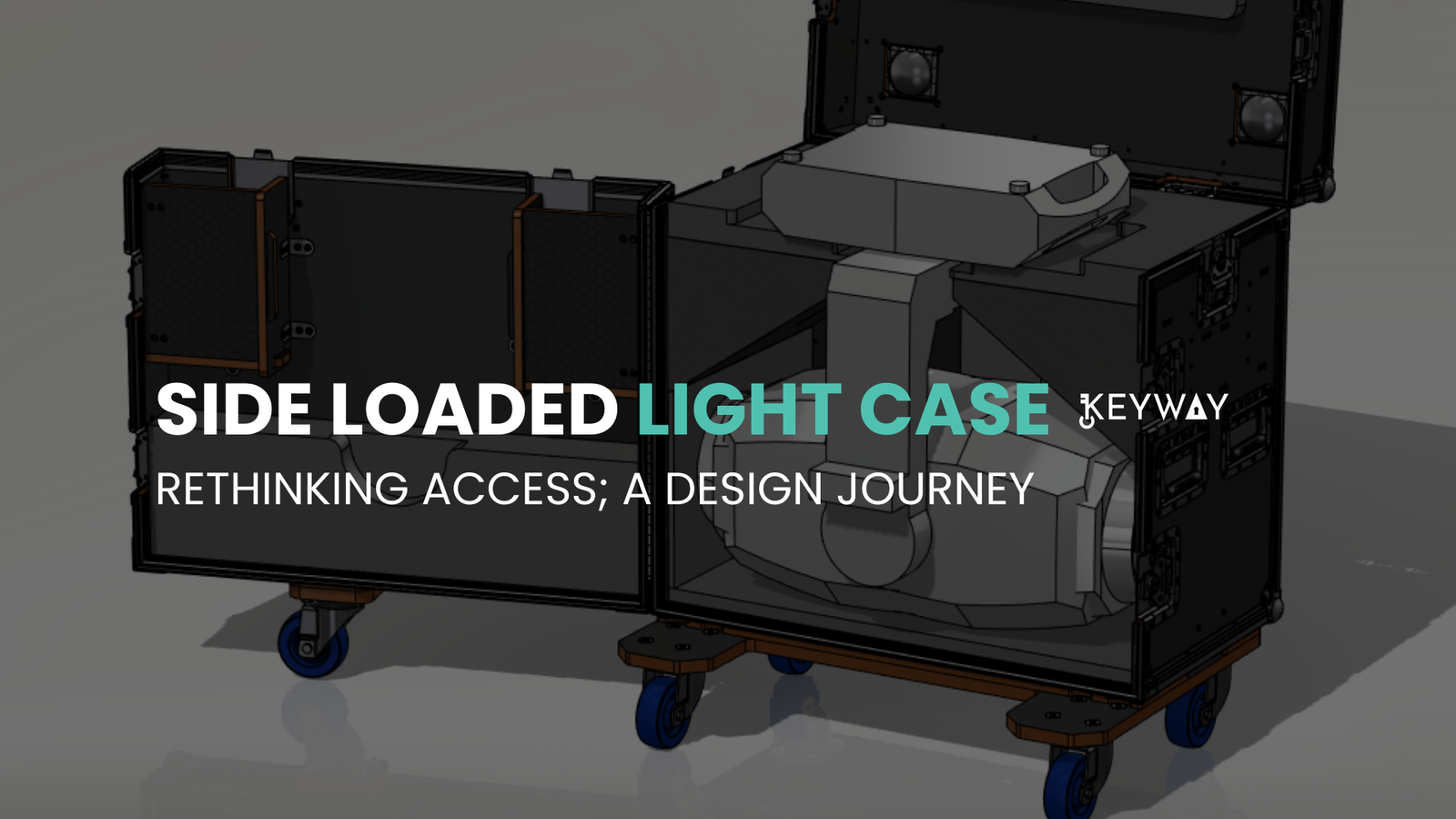
Flight case design isn’t just about protection—it’s also about usability and logistics. When we were approached to create a custom case for the Chauvet Maverick Storm 4 Profile, one of the largest moving head lights in its class, the standard top-loading configuration quickly proved impractical. The fixture’s size, weight, and the way it needs to be handled led us to an alternative approach: a side-loaded road case.

transport case for a moving head light, front view

Input Conditions and Design Constraints

The client’s key requirements were clear:

  • The case had to fit the Maverick Storm 4 Profile with minimal footprint.

  • It needed to provide safe, repeatable loading and unloading with reduced risk of damage or injury.

  • Structural durability had to meet touring-grade expectations.

  • The overall weight and external dimensions should stay within manageable limits for transport and handling.

Our design team also factored in the light’s center of gravity, the accessibility of rigging points, and the use-case scenarios for both indoor and outdoor productions.

The Path to a Side-Loaded Solution

Initial modeling in SolidWorks revealed challenges with vertical loading. The height required for lifting the fixture in and out safely would increase the overall case height significantly, complicating logistics. Additionally, top-loading raised risks of improper handling, particularly in fast-paced environments like festivals and live events.

By shifting to a side-loading design, we eliminated the need for vertical lifting altogether. The light could now be slid in and out using custom-milled runners, padded guides, and foam support that aligned with its frame. This reduced the handling time and the potential for accidental impact or misalignment.

Ensuring Structural Integrity

A side door introduces a different stress profile than top-mounted lids. To ensure structural performance, we reinforced the internal framing around the access door and introduced load-distribution ribs to resist flex during transit. Every latch and hinge was rated for repeated use under rugged conditions. We also ran basic FEA simulations in SolidWorks to assess door flex under load and confirm the frame’s torsional strength.

Corner protectors, recessed hardware, and edge extrusions were carefully integrated to meet ATA standards while maintaining clean aesthetics.

The Importance of This Design in the Industry

Side-loaded cases aren’t new, but they are underutilized in larger fixture logistics. This case sets a precedent for designing around operational workflows, not just equipment dimensions. As moving head lights become more powerful—and larger—designing for ergonomics, efficiency, and safety becomes essential.

For touring companies, rental houses, and production crews, this case offers:

  • Faster setups and teardowns

  • Reduced risk of damage during handling

  • Lower lifting fatigue for technicians

This project exemplifies how thoughtful design, supported by professional CAD workflows, can solve real-world challenges and elevate the standard for road case engineering.

Complete Guide to Design for Manufacturability in Plastic Injection Molding

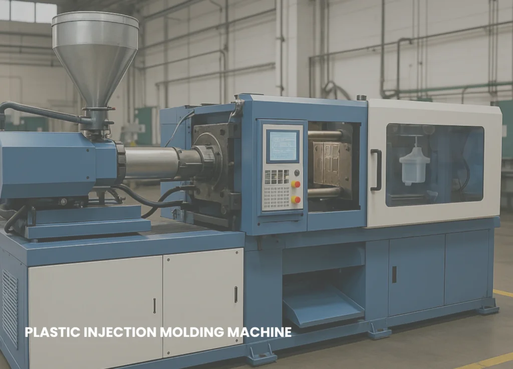
Plastic injection molding is one of the most widely used manufacturing processes for mass-producing plastic parts. However, the success of this process doesn’t just depend on tooling and machinery—it begins with a well-thought-out design. That’s where Design for Manufacturability (DFM) comes in.

In this comprehensive guide, we’ll cover the key principles of DFM for plastic injection molding, best practices for optimizing part designs, common pitfalls, and how good design choices can lead to cost-effective, high-quality production.


🔍 What is Design for Manufacturability (DFM)?

Design for Manufacturability (DFM) is the practice of designing parts in a way that simplifies the manufacturing process, reduces production costs, minimizes defects, and ensures consistent quality. In the context of plastic injection molding, DFM plays a crucial role in mold design, cycle time, material selection, and tool longevity.


⚙️ Why DFM is Critical in Injection Molding

  • 🚀 Faster Production: Optimized parts can be molded more efficiently with fewer complications.

  • 💰 Lower Costs: Minimizes scrap, tooling rework, and maintenance.

  • 📦 Better Quality: Reduces warpage, sink marks, and defects.

  • 🔄 Streamlined Assembly: Improves compatibility with downstream assembly processes.


🧱 Key Principles of DFM in Plastic Injection Molding

1. Wall Thickness Uniformity

Avoid uneven wall thickness, which can cause sink marks, warpage, and voids. Maintain consistent wall thickness (ideally 2–4 mm) and transition gradually when variation is needed.

👉 Tip: Use ribs instead of thick sections to add strength without increasing wall thickness.


2. Draft Angles

Incorporate draft angles (typically 1°–3°) on vertical walls to allow for smooth ejection from the mold.

🔧 Without draft, parts can stick to the mold, causing damage or requiring excessive ejection force.


3. Ribs and Bosses

Use ribs for structural support and bosses for fastening points, but ensure:

  • Ribs are no more than 60% of the wall thickness

  • Bosses are supported by ribs to prevent sink marks

📐 Proper rib design enhances strength without compromising part quality.


4. Fillets and Radii

Sharp corners can lead to stress concentrations and difficulty in mold filling. Use fillets (rounded corners) to improve material flow and reduce stress.

🌊 Flow-friendly designs = less turbulence = fewer defects.


5. Undercuts

Undercuts increase mold complexity and cost. Avoid them where possible or use:

  • Sliding cores

  • Lifters

  • Collapsible cores

🛠️ Every undercut adds cost—design with simplicity in mind.


6. Parting Line Considerations

The parting line is where the two halves of the mold meet. Place it:

  • Along flat surfaces

  • Away from cosmetic areas

  • To aid ejection and reduce flash

💡 Early identification of the parting line saves tooling headaches later.


7. Material Selection

Choose the right plastic material based on:

  • Mechanical properties (flexibility, strength)

  • Chemical resistance

  • Appearance

  • Cost

🧪 Common materials: ABS, Polypropylene (PP), Nylon (PA), Polycarbonate (PC), and more.


8. Gate Location and Type

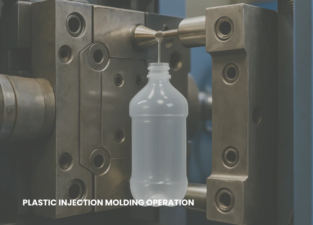
The gate is the entry point for molten plastic. Its placement affects flow, weld lines, and appearance. Types include:

  • Edge gates (common)

  • Submarine gates (auto-trim)

  • Hot tip gates (cosmetic parts)

🌀 Proper gate design = balanced flow + fewer defects.


9. Ejector Pin Placement

Pins push the part out of the mold. Poor placement can leave marks or deform the part.

📍 Best practice: place ejectors on hidden or non-cosmetic areas.


10. Tolerancing

Injection-molded parts shrink as they cool. Overly tight tolerances increase cost and difficulty. Use:

  • Standard tolerances where possible

  • Critical tolerances only where function demands it

📏 Design for the real-world, not just the CAD model.


🧰 Tools to Assist with DFM

Use CAD tools and mold flow simulation software to verify design choices before tooling:

  • 🧪 Autodesk Moldflow

  • 🛠️ SolidWorks Plastics

  • 📊 Simcenter Moldex3D

  • 🧬 PTC Creo Mold Analysis

These tools help visualize plastic flow, cooling behavior, pressure points, and more.


🚫 Common DFM Mistakes to Avoid

  • Neglecting draft angles

  • Ignoring flow and cooling patterns

  • Overcomplicating the geometry

  • Not collaborating with mold engineers early

  • Choosing inappropriate materials


🧩 Collaborating with Tooling Engineers Early

Early engagement between product designers and mold/tooling engineers reduces costly revisions. Toolmakers can:

  • Suggest parting line placements

  • Identify moldability issues

  • Estimate tooling lead time and cost

👥 Good design happens when engineering and manufacturing teams work together.


📉 Cost-Reduction Tips Through DFM

  • Combine multiple parts into one mold where possible

  • Use family molds for similar components

  • Design for automation (robot-friendly geometry)

  • Eliminate non-essential features or aesthetics

💡 DFM isn’t just about quality—it’s a direct path to higher profit margins.


🔮 The Future of DFM in Plastic Injection Molding

With the rise of AI-powered design tools, generative design, and digital twins, DFM is becoming even more intelligent. These tools allow:

  • Real-time manufacturability feedback

  • Automated optimization

  • Simulation of thousands of iterations in minutes

🧠 The future is smart, connected, and automated.


✅ Conclusion

Design for Manufacturability in plastic injection molding is not a one-time consideration—it’s a mindset embedded throughout the product development cycle. By focusing on optimized wall thickness, draft angles, gate placement, and material selection, you can:

  • Accelerate production timelines

  • Improve product quality

  • Lower manufacturing costs

  • Extend mold life

Whether you’re designing a consumer product, industrial component, or medical device—applying DFM principles is essential for competitive, scalable manufacturing.