In the production field, a product is as good as the drawing that is an engineering definition of the product. Although CAD software today provides engineers with the capability to develop sophisticated 3D designs, engineering drawings are still well developed and utilized by production teams to produce parts with high precision and efficiency. The low quality of the drawn is, unfortunately, one of the most frequent reasons of delays in the production, quality problems, and high cost of production.
Manufacturers are prone to poor drawings, vague tolerances, lack of specifications, and ambiguous dimensions. These issues slack the manufacturing process and result in repeated inter-communication between engineers and the shop-floor teams. With clear, structured, and practical drawings, the manufacturers are able to manufacture parts more quickly, and with minimal mistakes and reduced expenses.
This is a guide on how to design engineering drawings that manufacturers are thrilled about-documents that convey the design desire clearly and avoid ambiguity and assist in efficient production.
Why Clear Engineering Drawings Matter in Manufacturing
Engineering drawings provide a transition between design and manufacturing. Their task is to take design intent and convert it into operational instructions that can be followed by machinists, fabricators, welders and quality inspectors. Where such communication is not clear, then there will be production problems.
The slightest detail that is missed in a drawing can lead to significant manufacturing problems. As an illustration, uncertainty in the tolerance would force the production teams to stop working and seek clarification. Absence of surface finish requirements can lead to poor quality of products. When the dimensions are not clear, then either scrap parts or expensive rework may be as a result.
Beyond the advantages that manufacturers gain in the event that drawings are well-structured and complete they have:
- Faster production setup
- Reduced machining errors
- Lower scrap and rework rates
- Better consistency of products.
- Increased interaction between manufacturing and design teams.
Finally, good drawings minimize the friction in manufacturing and enhance the efficiency.
The Role of Engineering Drawings in Cost Control
When designing products, many engineers are interested in product performance, however documentation quality is an important factor in the cost of manufacture. The poor documentation usually results in unaccounted costs like the delays in production, redundant checks, and unwarranted machining processes.
Detailed drawings enable production departments to know exactly what should be produced and how accurate every detail should be. This will avoid over-processing and also unnecessary tight tolerances.
Cost wise, good documentation assists the manufacturers:
- Choose the right machining strategies.
- Eliminate unnecessary precision requirements.
- Avoid production guesswork
- Reduce the delay in communication.
Properly developed drawings eventually foster Design for Manufacturing (DFM) philosophy in that the design is usable on the shop floor and is efficient.
Key Elements of Manufacturer-Friendly Engineering Drawings
To create drawings that manufacturers truly appreciate, engineers must focus on clarity, completeness, and practicality. Several key elements determine whether a drawing is easy or difficult to interpret.
- Clear and Logical Dimensioning
The presentation of dimensions is one of the most significant issues of an engineering drawing. The incorrectly located or unnecessary dimensions’ cause confusion and the possibility of errors in machining.
The part should be defined clearly in all dimensions without requiring the machinists to do some computations on the missing values. All the critical features should be measurable and have a clear datum point of reference.
Engineers must consider the following pragmatic rules when making dimensions:
- Locate dimensions external to the part as much as possible to enhance readability.
- Do not duplicate dimensions that can give conflicting meanings.
- Reference dimensions of uniform data.
- Be sure that necessary features needed to manufacture are defined.
Error-free dimensioning minimizes errors during interpretation and accelerates the process of machining setup.
- Functional Tolerance Instead of Over-tolerance
One of the most important decisions in an engineering documentation is the tolerance specification. Unluckily, tolerances are unnecessarily tight in many of the drawings which adds to the cost of manufacturing but does not add any functionality.
All the dimensions do not demand high precision. Features that will have an impact on performance, assembly fit, or safety should only be tightened. Variables that are not critical are to be given reasonable variation.
Tolerances are also tighter than required, then machining speeds will have to be slower and further inspection measures are needed. This makes the production time and cost high.
An artist-friendly drawing guarantees that tolerances are used reasonably and on demand only. Functional tolerance enhances efficiency in manufacturing products and improving product quality.
- Clear Surface Finish Specifications
The machining methods and time of production is directly affected by surface finish requirements. When the drawings contain case-wise surface finishes they often contain unnecessarily fine areas on the surface finish of entire parts.
Engineers ought to identify the surfaces which do impact on the performance instead of defining tight finishes everywhere. As an example, better finishes are generally needed on sealing surfaces, sliding interfaces, bearing contact areas, and other areas can easily be left with a standard machine finish.
Clear surface finish specifications would assist the manufacturers to choose the right machining plan, as well as prevent unnecessary surface finishing operations.
- Material and Treatment Specifications
The manufacturers rely on drawings to know precisely what material should be utilized and whether any other treatment is necessary or not. Lacking or poor material specifications may lead to delays in procurement and confusion in production.
On a good engineering drawing, it is clearly defined:
- Material grade and standard
- Heat treatment specifications.
- Surface coatings or plating
- Hardness or mechanical property specifications.
The provision of such details will guarantee the end product to be of functional and durable features.
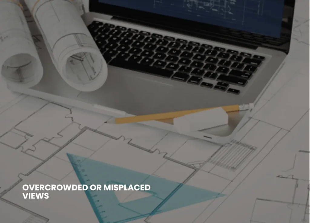
- Readable Layout and Organized Information
Even technically correct drawings would turn tough to decode in case they are not arranged well. Congested drawings containing too many notes, overlapping sizes and views can be disorienting to production teams.
Decipherable drawings are based on a systematic pattern that is more concerned with clarity.
The following are some common practices concerning formatting:
- Keeping sufficient distance between dimensions.
- The utilization of unvarying text size and the forms of annotations.
- Organizing notes logically
- Offering clear section views of complicated features.
An organized and well-arranged drawing layout carries the machinists and fabricators to learn the design intent within a short time.
Common Engineering Drawing Mistakes That Frustrate Manufacturers
Even seasoned engineers occasionally come up with drawings that end up making it more difficult to manufacture. The knowledge of typical mistakes in documentation may allow avoiding the expensive production problems.
The common issues are:
- The absence of dimensions or geometry definitions.
- Intersecting dimensions that decrease readability.
- Unjustified excessive tolerances.
- Absence of datum reference points of essential measurements.
- Lacks of notes on surface treatment or finishes.
- Indistinct or archaic revision information.
These errors usually lead to delays in production, clarification, and possible quality problems.
Manufacturers like to have drawings which are clear and not subject to interpretation.
Best Practices for Creating Cost-Effective Engineering Drawings
To ensure drawings are both clear and manufacturing-friendly, engineers should adopt a documentation mind-set that prioritizes practicality.
Several best practices can significantly improve drawing quality:
- Review drawings from a machinist’s perspective before release
- Conduct internal drawing reviews within the engineering team
- Follow established drafting standards consistently
- Use standardized symbols and GD&T conventions
- Communicate with manufacturing teams during design development
By incorporating feedback from production teams, engineers can continuously improve documentation quality.
How Engineering Drawings Support Efficient Production
Clarity of drawings does not only specify the size but also assists production groups in strategizing machining plans, developing fixtures and devising inspection plans. Drawing conveying design intent can be useful in creating a manufacturing process that is faster and more predictable.
As an example, a clear datum structure enables machinists to index parts without errors and to maintain measurements. This is because clearly defined tolerances assist quality inspectors with the determination of whether the parts comply with specifications without the undue complexity.
On the contrary, ambiguous drawings compel manufacturers to make assumptions, thus, putting more risk and variability in production.
Good documentation enhances effective working process of raw material preparation to the end product inspection.
The Importance of Collaboration Between Design and Manufacturing
When design teams work closely with manufacturing teams, engineering documentation is enhanced in many ways. Machinists, fabricators, and quality inspectors are regularly a great source of information on how the drawings can be refined to develop into useful production.
The early cooperation enables the engineers to:
- Determine possible production issues.
- Simplify complex features
- Optimize tolerances
- Enhance the availability of inspection.
In case of engineering and manufacturing co-operation, there is more realistic drawing and friendly to production.
The Long-Term Benefits of High-Quality Engineering Documentation
To produce effective engineering drawings, there is a lot of labor invested, but the benefits of the same are substantial in the long run. Good records enhance efficiency in production and also minimize errors and enhance communication among the departments.
Companies with emphasis on good documentation tend to have:
- Faster production setup
- Lower scrap and rework rates
- Better consistency of products.
- More successful partnering with suppliers.
- Minimized engineering change orders.
Documentation quality may have a direct effect on profitability in competitive manufacturing industries.
Final Thoughts: Designing Drawings for the Shop Floor
Engineering drawings must not be designed to only verify the design but should be designed to be manufacturing friendly. The most effective drawings convey design intent and help to sustain the efficient production processes.
The last, but not the least, question that engineers need to answer before they release any drawing is a simple question, yet a strong question: Can a manufacturer comprehend this drawing immediately and create the part without any misunderstandings?
When the response is yes, then the drawing is performing its task.
Well-organized engineering documentation converts the complex designs to manufactured products. By making drawings carefully, manufacturers are able to concentrate on their core competency, which is developing quality products in an effective and reliable manner.
Technical documents are not the only good engineering drawings. It is their basis of successful manufacturing.


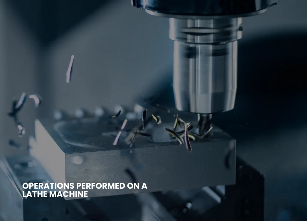

 utomation, machining was intensive in terms of skill and rich setting-to-do experience. Machinists also had to know the machines by feel, by listening to sounds of cutting, by touching vibrations and manually adjusting the parameters. These are the skills which had been acquired through several years of experience in manual lathes, milling machines and grinders.


 ; paid such as PowerInspect, to do inspection.